
Energy-saving control method and system for revolving speed of engine

A technology for engine speed and energy-saving control, applied in engine control, machine/engine, governor, etc., to solve problems affecting system working stability and driving comfort, changes in driving speed requirements, and inability to take into account driving conditions. , to avoid frequent and large changes, improve driving comfort, and improve the time of the economic zone

Active Publication Date: 2016-06-01
WEICHAI POWER CO LTD
View PDF6 Cites 13 Cited by
  • Summary
  • Abstract
  • Description
  • Claims
  • Application Information

AI Technical Summary

Problems solved by technology

However, when a typical closed traveling hydraulic system operates normally (such as bulldozers and loaders), not only does the driving speed change, but the load also changes continuously. The engine speed calculated according to the above method will inevitably fluctuate continuously. Affect the stability of the system work and driving comfort
Moreover, the calculation of the engine speed setting value according to the above method will only take into account the purpose of economy, and will not adopt those speed values ​​with high speed and poor fuel consumption, so that it is impossible to take into account the driving situation with low load and high speed requirements (fast driving on flat roads) ), not suitable for closed hydraulic travel system

Method used


Image

  • Energy-saving control method and system for revolving speed of engine
  • Energy-saving control method and system for revolving speed of engine
  • Energy-saving control method and system for revolving speed of engine

Examples


Embodiment Construction

[0051] Embodiments of the present invention will be described in detail below with reference to the accompanying drawings.

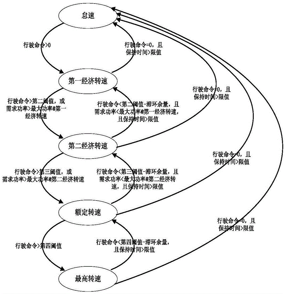
[0052] Such as figure 1As shown, the present invention provides an energy-saving control method for engine speed, including: obtaining the required driving speed and load required power; .

[0053] The basic characteristic of the engine is that the external characteristic torque of the engine is the largest at a certain speed value in the middle speed zone. At the same time, in the middle speed range, which is also the region with the best engine efficiency characteristics, the fuel required to output the same power in this speed range is the least. As the speed increases until the rated speed, although the external characteristic torque of the engine is decreasing, the output power of the engine is gradually increasing, and the economy is gradually getting worse. From the rated speed to the maximum speed, the external characteristic torque of the eng...


PUM


Abstract

The invention relates to an energy-saving control method and system for revolving speed of an engine. The method comprises the following steps: acquiring required running speed and load required power; and setting a revolving speed value of the engine to be minimum revolving speed on the premise of meeting the required running speed and the load required power. By the energy-saving control method and system for the revolving speed of the engine, the engine runs at economical revolving speed as much as possible on the promise of meeting a vehicle speed requirement and a power requirement, so that the purpose of saving fuel is achieved. Meanwhile, when the revolving speed set value of the engine is changed, a hydraulic system is adjusted in real time so as to guarantee stable running speed and link before and after change of the revolving speed, and stability and driving comfort are good. A power requirement serves as a first priority, and the revolving speed of the engine can be relatively high when high speed or large torque is required. Therefore, a vehicle can meet optional speed requirements. But the required speed of the vehicle is not maximum in most cases, and the advantage of fuel saving can also be played fully.

Description

technical field [0001] The invention relates to the technical fields of construction machinery and agricultural machinery, in particular to an energy-saving control method and system for engine speed. Background technique [0002] In hydrostatic applications, the control of the engine and the hydraulic system are largely independent of each other. During the full range adjustment of the hydraulic system, the engine speed is either maintained at a fixed value or increased with the increase of vehicle speed. Therefore, it is difficult to balance the economy and power of the engine. [0003] In the prior art, there are energy-saving control methods and systems applied to truck cranes. The control target is a closed system composed of a variable pump and a fixed-quantity motor to drive the crane up and down. Its energy-saving control method is to select the speed with the lowest fuel consumption per unit time from the engine speed range according to the current load signal, an...

Claims


Application Information

Patent Timeline
IPC IPC(8): F02D29/02
CPCF02D29/02F02D31/001
Inventor 赵金光陈岩赵华王高峰刘彬李云霞
Owner WEICHAI POWER CO LTD
Learn More