
Sludge processing system with low energy consumption and processing method thereof

A sludge treatment and low energy consumption technology, which is applied in the direction of temperature control sludge treatment, dehydration/drying/thickening sludge treatment, oxidation treatment of sludge, etc., can solve the problems of large energy consumption and low treatment efficiency, and achieve reduction Effects of production cost, activation energy reduction, and energy consumption reduction

Active Publication Date: 2016-06-01
北京首创大气环境科技股份有限公司
View PDF3 Cites 7 Cited by
  • Summary
  • Abstract
  • Description
  • Claims
  • Application Information

AI Technical Summary

Problems solved by technology

[0014] The purpose of the present invention is to propose a low energy consumption sludge treatment system and treatment method for the problems of large energy consumption and low treatment efficiency in the process of sludge wet oxidation treatment

Method used


Image

  • Sludge processing system with low energy consumption and processing method thereof

Examples


Embodiment 1

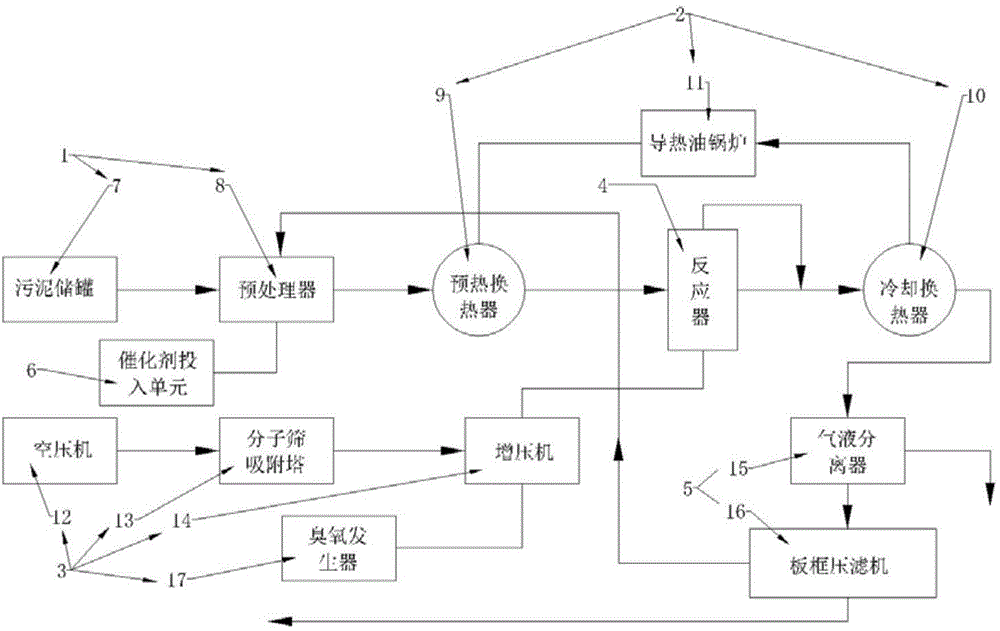
[0040] The present invention provides a sludge treatment system with low energy consumption. The treatment system includes a pretreatment unit 1, a heat exchange unit 2, an oxidation matrix unit 3, a reactor 4, a separation unit 5, and a catalyst input unit 6. The reactor 4 is respectively connected with the heat exchange unit 2 , the oxidation substrate unit 3 and the separation unit 5 , and the pretreatment unit 1 is connected with the heat exchange unit 2 , the separation unit 5 and the catalyst input unit 6 respectively.

[0041]The pretreatment unit 1 includes a sludge storage tank 7 for storing sludge, a pretreatment tank 8 connected to the sludge storage tank 7, a solid pump for transporting sludge, and a set in the pretreatment tank 8 mixer.

[0042] In the pretreatment unit 1, the sludge with a water content of 75% to 85% in the sludge storage tank 7 is injected into the preprocessor 8 with a solid pump, and the liquid phase of the separation unit 5 is returned to the...

Embodiment 2

[0066] The present invention also provides a low-energy sludge treatment method, said treatment method comprising the steps of:

[0067] A. The sludge stored in the sludge storage tank 7 is injected into the pretreatment tank 8 with a solid pump, mixed with the liquid phase reflux water of the separation unit 5 in the pretreatment tank 8, and the catalyst is added through the catalyst input unit 6, and the preparation into a material with a moisture content of 90%.

[0068] In the sludge storage tank 7, the sludge with a water content of 75% to 85% is mixed with the liquid-phase backflow water to form a material with a water content of 90%. The liquid-phase circulating water is acidic with a pH of 4 to 5. Under the action of acid, the sludge will break down, causing some cells to dissolve and free water to increase. Moreover, due to the high temperature of the return water, the original sludge will be preheated. . Under the synergy of these aspects, the fluidity of the mixed...


PUM


Abstract

The invention relates to a sludge processing system with low energy consumption and a processing method thereof. A hydrothermal oxidation principle is adopted, ozone is added in an oxidation medium, then organisms in sludge can be thoroughly and rapidly oxidized in a liquid phase manner, the reaction time is shortened, so that the energy consumption is reduced. At the same time, an initial material is preheated by reacted materials by using an efficient heat exchanger, and due to adoption of a sealed heat exchange structure, not only is the situation that heat energy is lost as a great deal of steam is carried away when the air is directly discharged avoided, but also steam can be reduced, the energy for phase change heat consumption of water can be reduced, the energy investment can be reduced, and the operation cost can be reduced. In addition, due to addition of a Cu-Fe-Ce catalyst or a noble metal catalyst in sludge, the reaction activation energy is reduced, the required temperature for reaction is reduced, the energy consumption is reduced, and the production cost is lowered.

Description

technical field [0001] The invention relates to the field of sludge treatment, in particular to a sludge treatment system and a treatment method with low energy consumption. Background technique [0002] Since entering the "Eleventh Five-Year Plan", my country's sewage treatment industry has developed rapidly, and the sewage treatment capacity and treatment rate have increased rapidly, which has brought about a rapid increase in sludge production. According to the data of the Ministry of Housing and Urban-Rural Development, by the end of 2009, the national urban sewage treatment volume reached 28 billion cubic meters, and the production of wet sludge (with a moisture content of 80%) exceeded 20 million tons. According to the survey results, 80% of the sludge produced by my country's sewage treatment plants has not been properly treated, and the random accumulation of sludge and the pollution and re-pollution problems caused by it have become prominent and have aroused social...

Claims


Application Information

Patent Timeline
IPC IPC(8): C02F11/12C02F11/18C02F11/06
Inventor 郑向军王薇武晓剑朱贵徽张平敏薛峰李婷
Owner 北京首创大气环境科技股份有限公司
Learn More