
Automatic exposure machine for flexible printed circuit board

A technology of automatic exposure and soft board, which is applied in the direction of photomechanical equipment, microlithography exposure equipment, photoplate making process exposure device, etc., to achieve the effects of good stability, accelerated development process, and high exposure accuracy

Active Publication Date: 2016-05-25
深圳市研宝工业科技有限公司
View PDF4 Cites 7 Cited by
  • Summary
  • Abstract
  • Description
  • Claims
  • Application Information

AI Technical Summary

Problems solved by technology

[0004] The technical problem to be solved by the present invention is to overcome the deficiencies of the above-mentioned prior art, and provide an automatic exposure machine for flexible boards, which can expose both sides of the flexible boards put into the machine at one time, so as to avoid the difficulty of alignment and easy deformation of the flexible boards. position problems, thereby improving production efficiency

Method used


Image

  • Automatic exposure machine for flexible printed circuit board
  • Automatic exposure machine for flexible printed circuit board
  • Automatic exposure machine for flexible printed circuit board

Examples


Embodiment Construction

[0034] The present invention will be further described below in conjunction with the accompanying drawings and specific embodiments. Terms such as "upper", "lower", "left", "right", "middle" and "one" quoted in the preferred embodiment are only for convenience of description, and are not used to limit the scope of the present invention. The scope of implementation and the change or adjustment of its relative relationship shall also be regarded as the scope of implementation of the present invention without substantive changes in technical content.

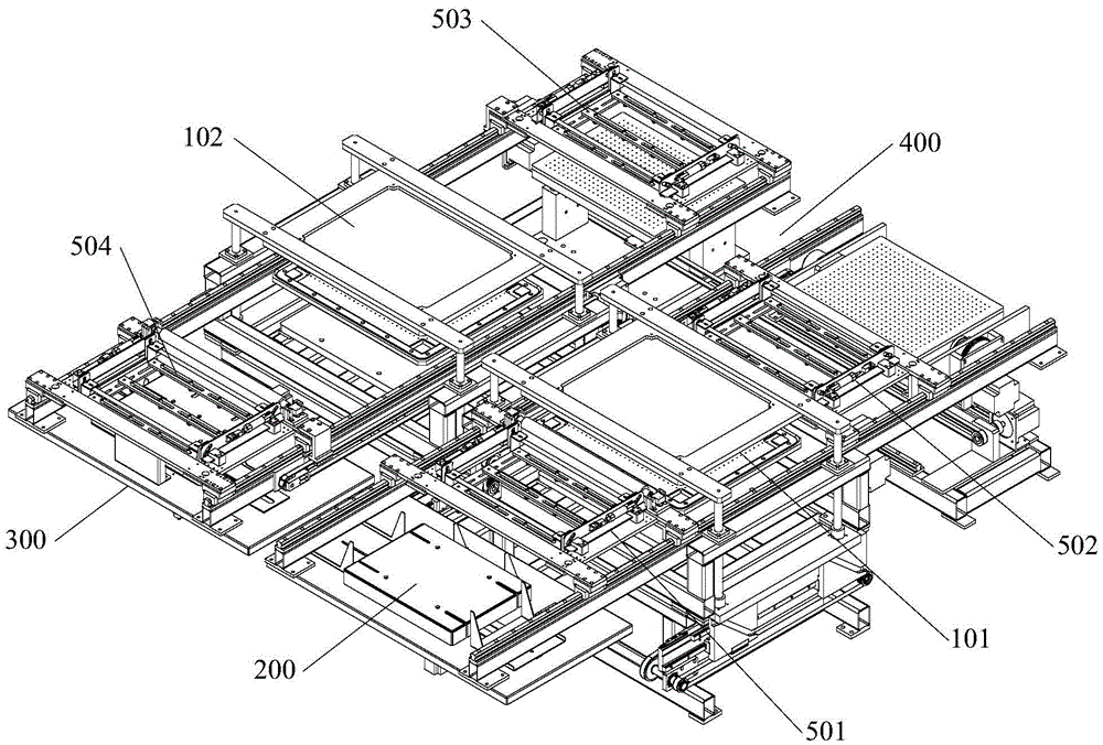
[0035] See figure 1 , an automatic exposure machine for flexible boards designed in a preferred embodiment of the present invention, which mainly includes: two exposure mechanisms, a material feeding and stacking mechanism 200, a material receiving and stacking mechanism 300, a plate turning mechanism 400 and four A suction cup assembly, the first and second exposure mechanisms are arranged side by side, and the feeding and stacki...


PUM


Abstract

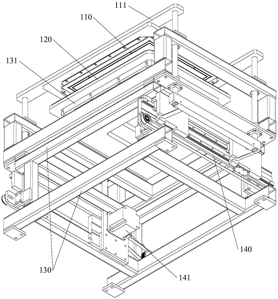
The invention relates to an automatic exposure machine for a flexible printed circuit board. The automatic exposure machine comprises a first exposure mechanism and a second exposure mechanism, a material feeding stacking mechanism and a material receiving stacking mechanism, a plate overturning mechanism and a sucking disc assembly, wherein the first exposure mechanism and the second exposure mechanism are arranged side by side for exposing both sides of the flexible printed circuit board respectively; the material feeding stacking mechanism and the material receiving stacking mechanism are respectively arranged in front of the first exposure mechanism and in front of the second exposure mechanism; the plate overturning mechanism is arranged at the back of the two exposure mechanisms; the sucking disc assembly is used for conveying the flexible printed circuit board among the mechanisms; the plate overturning mechanism comprises an overturning assembly capable of rotating the flexible printed circuit board by 180 degrees and a sliding plate assembly for driving the flexible printed circuit board to move left and right corresponding to the first exposure mechanism and the second exposure mechanism; each exposure mechanism comprises a supporting assembly, exposure glass arranged above the supporting assembly, an aligning platform surface which is positioned below the exposure glass and can be matched with the exposure glass to clamp the flexible printed circuit board between the aligning platform surface and the exposure glass and a glass opening and closing assembly for driving the exposure glass to move up and down, and an aligning mechanism for driving the flexible printed circuit board to slide or rotate on the plane is arranged on the bottom surface of the aligning platform surface. According to the automatic exposure machine for the flexible printed circuit board, exposure for both sides of the flexible printed circuit board can be completed once, and the problems of the flexile printed circuit board such as aligning difficulty and easy deflection are avoided, so that the production efficiency is improved.

Description

technical field [0001] The invention is applied to the field of exposure process equipment in the printed circuit board industry, and more specifically relates to an automatic exposure machine for flexible boards. Background technique [0002] The exposure process is to transfer the circuit image on the negative film to the substrate. For the exposure machine, the exposure accuracy is very high, and any error may cause the failure of the image pad printing. In the exposure process of flexible printed circuit boards, since both the film and the substrate are soft plates, it is difficult to align them; The deviation will cause the quality of the exposure process to be unstable, which will eventually lead to a decrease in processing efficiency and an increase in production cost. [0003] In view of this, how to provide a flexible board exposure machine with high exposure accuracy and no displacement is a technical problem to be solved urgently in the industry. Contents of th...

Claims


Application Information

Patent Timeline
IPC IPC(8): G03F7/20
CPCG03F7/2032
Inventor 陈宁
Owner 深圳市研宝工业科技有限公司
Learn More