Omnidirectional reflector of cascaded plasma photonic crystal structure
An omnidirectional reflection, plasma technology, applied in the direction of light guide, optics, instruments, etc., can solve the problems of complex structure and the width of omnidirectional band gap needs to be further improved.
- Summary
- Abstract
- Description
- Claims
- Application Information
AI Technical Summary
Problems solved by technology
Method used
Image
Examples
Embodiment 1
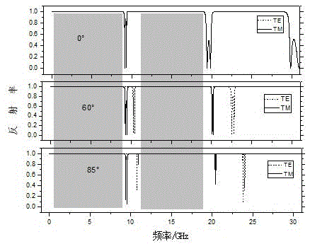
[0020] see Figure 1~Figure 4 , the omnidirectional reflector of this cascaded plasmonic photonic crystal structure can be expressed as (F 3 ) 3 / (T 2 ) 2 , that is, the multilayer structure of A and P arranged in a third-order Fibonacci sequence with three periods along the incident direction of the beam, with (F 3 ) 3 Indicates that superscript 3 and subscript 3 are the period and order of the Fibonacci sequence respectively, and the multi-layer structure of B and P` with two periods arranged in the second-order Thue-Morse sequence, with (T 2 ) 2 Indicates that superscript 2 and subscript 2 are the Thue-Morse sequence period and order respectively; where, A is the optical film medium, P is the plasma material layer, B is the optical film medium, and P` is the plasma material layer.
Embodiment 2
[0022]This embodiment is basically the same as Embodiment 1, and its special features are as follows: the omnidirectional reflector of this cascaded plasma photonic crystal structure, its third-order Fibonacci sequence F 3 =F 2 f 1 , where F 2 =F 1 f 0 , the first two Fibonacci sequences are F 0 ={AP} and F 1 ={P}, then F 2 =F 1 f 0 ={PAP},F 3 =F 2 f 1 ={PAPP}. Thue-Morse sequence T of order 2 2 = T 1 T` 1 , where T` 1 for pair T 1 according to Rule negation operation. start sequence T 1 ={BP`P`}, then T` 1 ={P`BP`},T 2 = T 1 T` 1 ={BP`P`P`BP`}. In addition, the optical thicknesses of the optical film dielectric layers A and B are equal or not; the optical thicknesses of the plasma layers P and P` are equal or not; and the plasma frequencies ω of the plasma layers P and P` p and ω p` The same, or not; the collision frequency γ of the plasma layers P and P` p and gamma p` the same, or not the same.
Embodiment 3
[0024] The omnidirectional reflector of the cascaded plasmonic photonic crystal structure of this embodiment is as attached figure 1 As shown in the structure, the overall structure consists of three periodic quasi-periodic structures arranged in a third-order Fibonacci sequence (F 3 ) 3 and 2 periods of quasi-periodic structures arranged in a 2nd-order Thue-Morse sequence (T 2 ) 2 Cascading composition, specifically (F 3 ) 3 / (T 2 ) 2 . where (F 3 ) 3 is a Fibonacci quasi-periodic structure, the Fibonacci sequence F 3 =F 2 f 1 , F 2 =F 1 f 0 ;The first two sequences are F 0 ={AP} and F 1 ={P}, then F 3 ={PAPP};(T 2 ) 2 For the Thue-Morse quasi-periodic structure, the Thue-Morse sequence T 2 = T 1 T` 1 , T` 1 for pair T 1 according to Rule negation operation, starting sequence T 1 ={BP`P`}, then T` 1 ={P`BP`},T 2 = T 1 T` 1 ={BP`P`P`BP`}. A and B are optical film media with different refractive indices, and P and P' are plasma material layers. ...
PUM
 Abstract
Description
Claims
Application Information
 - R&D
- Intellectual Property
- Life Sciences
- Materials
- Tech Scout
- Unparalleled Data Quality
- Higher Quality Content
- 60% Fewer Hallucinations
Browse by: Latest US Patents, China's latest patents, Technical Efficacy Thesaurus, Application Domain, Technology Topic, Popular Technical Reports.
© 2025 PatSnap. All rights reserved.Legal|Privacy policy|Modern Slavery Act Transparency Statement|Sitemap|About US| Contact US: help@patsnap.com


