Manufacturing process of a plastic synchronous pulley

A technology of synchronous pulley and manufacturing process, which is applied to components with teeth, belts/chains/gears, portable lifting devices, etc. It can solve problems such as difficulty in ensuring assembly consistency, reducing the service life of molds, and difficult control of shrinkage ratio , to achieve the effect of ensuring the size and shape tolerance of each part, improving assembly consistency, and reducing process deformation

Active Publication Date: 2018-06-26
YINGKOU JINCHEN MACHINERY
View PDF6 Cites 0 Cited by
  • Summary
  • Abstract
  • Description
  • Claims
  • Application Information

AI Technical Summary

Problems solved by technology

However, during the molding process of plastic synchronous pulleys, there are process problems such as uneven tooth shape and spoke shrinkage, and the final product will have precision inaccuracies such as size and shape tolerances, making it unusable
[0004] In addition, in order to realize the closed rib of the synchronous pulley, it is necessary to use a complex mold structure for mold opening, which reduces the service life of the mold
Due to the limitation of the mold structure, the spokes of the synchronous pulley must expose the ribs, forming very unsightly convex and concave spaces, resulting in dead corners for dust storage
[0005] The radial runout of conventional injection-molded synchronous pulleys can only be controlled above 0.3mm; screaming noises often appear when the synchronous pulley teeth mesh with the synchronous belt teeth, which affects the transmission effect and sounds very uncomfortable
[0006] It is difficult to control the shrinkage ratio of the keyway hole or bearing hole of the synchronous pulley, and it is difficult to ensure the consistency of assembly

Method used


Image

  • Manufacturing process of a plastic synchronous pulley
  • Manufacturing process of a plastic synchronous pulley
  • Manufacturing process of a plastic synchronous pulley

Examples


Embodiment Construction

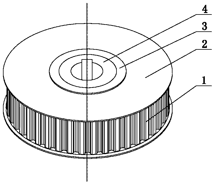
[0028] The plastic synchronous pulley of the present invention is characterized in that it includes a metal centering sleeve 4, a plastic synchronous pulley main body 1 is arranged outside the metal centering sleeve 4, and blocking pieces 2 are arranged on both sides of the plastic synchronous pulley main body 1.

[0029] Spokes 3 are provided on both sides of the main body 1 of the plastic synchronous pulley, and through holes 5 matching with the spokes 3 are provided on the blocking piece 2 .

[0030] The invention also provides a plastic synchronous pulley manufacturing process capable of ensuring high tooth profile precision and small deformation of the plastic synchronous pulley and ensuring consistent assembly of the synchronous pulley.

[0031] The manufacturing process of the plastic synchronous pulley of the present invention, step 1: set a metal centering sleeve 4 in the prefabricated pulley molding mold, inject nylon material into the prefabricated pulley molding mol...


PUM


Abstract

The invention provides a plastic synchronous pulley and a manufacturing process thereof, belongs to the technical field of mechanical transmission parts, and particularly relates to the plastic synchronous pulley and the manufacturing process thereof which are applied by photovoltaic solar cell module transmission equipment and a production line thereof. The invention provides the plastic synchronous pulley which is low in cost. The plastic synchronous pulley is characterized in that a metal centering sleeve is included, a plastic synchronous pulley body is arranged outside the metal centering sleeve, and blocking plates are arranged on the two sides of the plastic synchronous pulley body respectively. The invention further provides the manufacturing process of the plastic synchronous pulley, it can be guaranteed that the plastic synchronous pulley is high in tooth form precision and small in deformation, and the consistency of synchronous pulley assembling can be guaranteed. The manufacturing process of the plastic synchronous pulley is characterized in that the metal centering sleeve is arranged in a prefabricated belt pulley forming mold, and nylon materials are injected into the prefabricated belt pulley forming mold; a prefabricated member is obtained after cooling is conducted.

Description

technical field [0001] The invention belongs to the technical field of mechanical transmission components. In particular, it relates to a plastic synchronous pulley used in photovoltaic solar cell module transmission equipment and a production line thereof and a manufacturing process thereof. Background technique [0002] Synchronous pulley is a common part in mechanical transmission. For a long time, almost without exception, it is made of aluminum alloy material through cutting. During the processing, processes such as gear hobbing, gear shaping, and gear shaving are used. The processing technology is complicated and the cost is high. If it is too high, it will increase the cost of automatic transmission components. [0003] And in order to reduce the cost of automatic transmission components, those skilled in the art try to utilize the method for mold injection molding to produce plastic synchronous belt pulley. However, during the molding process of plastic synchronous...

Claims


Application Information

Patent Timeline
Patent Type & Authority Patents(China)
IPC IPC(8): F16H55/17B29C45/14
CPCB29C45/1459F16H55/171
Inventor 李敦信李福建訾沿宁李义升
Owner YINGKOU JINCHEN MACHINERY
Why Eureka
Try Eureka