
PP (Polypropylene) plastic injection molding machine

A technology for injection molding machines and plastics, applied in the field of injection molding machines, can solve problems such as reducing product quality, uneven heating, and screw wear of injection molding machines, and achieves the effects of saving costs and maintenance costs, improving production efficiency, and increasing transmission capacity.

Inactive Publication Date: 2016-05-25
苏州乔布注塑工业有限公司
View PDF6 Cites 7 Cited by
  • Summary
  • Abstract
  • Description
  • Claims
  • Application Information

AI Technical Summary

Problems solved by technology

However, before the material enters the injection molding machine, it is easy to accumulate and block, which will easily cause the blockage of the whole equipment, affect the production, increase the cost, and the uneven heating of raw materials will reduce the product quality; the screw is located in the center of the injection molding machine. , the main function is to complete the transmission of the mixture, plasticization, molding and other functions
At present, when the injection molding machine is working, the granular material is melted into a molten state by heating and the extrusion force of the screw, and then flows into the subsequent process for processing. Different areas of the screw have different functions, and different materials require different injection molding machines and matching equipment. Screw configuration processing, currently there is still a lack of injection molding machine screws that can change the thread shape of a certain part at any time, or a part of the injection molding machine screw is worn and only needs partial replacement or repair

Method used


Image

  • PP (Polypropylene) plastic injection molding machine
  • PP (Polypropylene) plastic injection molding machine
  • PP (Polypropylene) plastic injection molding machine

Examples


Embodiment Construction

[0016] The following will clearly and completely describe the technical solutions in the embodiments of the present invention with reference to the accompanying drawings in the embodiments of the present invention. Obviously, the described embodiments are only some, not all, embodiments of the present invention. Based on the embodiments of the present invention, all other embodiments obtained by persons of ordinary skill in the art without making creative efforts belong to the protection scope of the present invention.

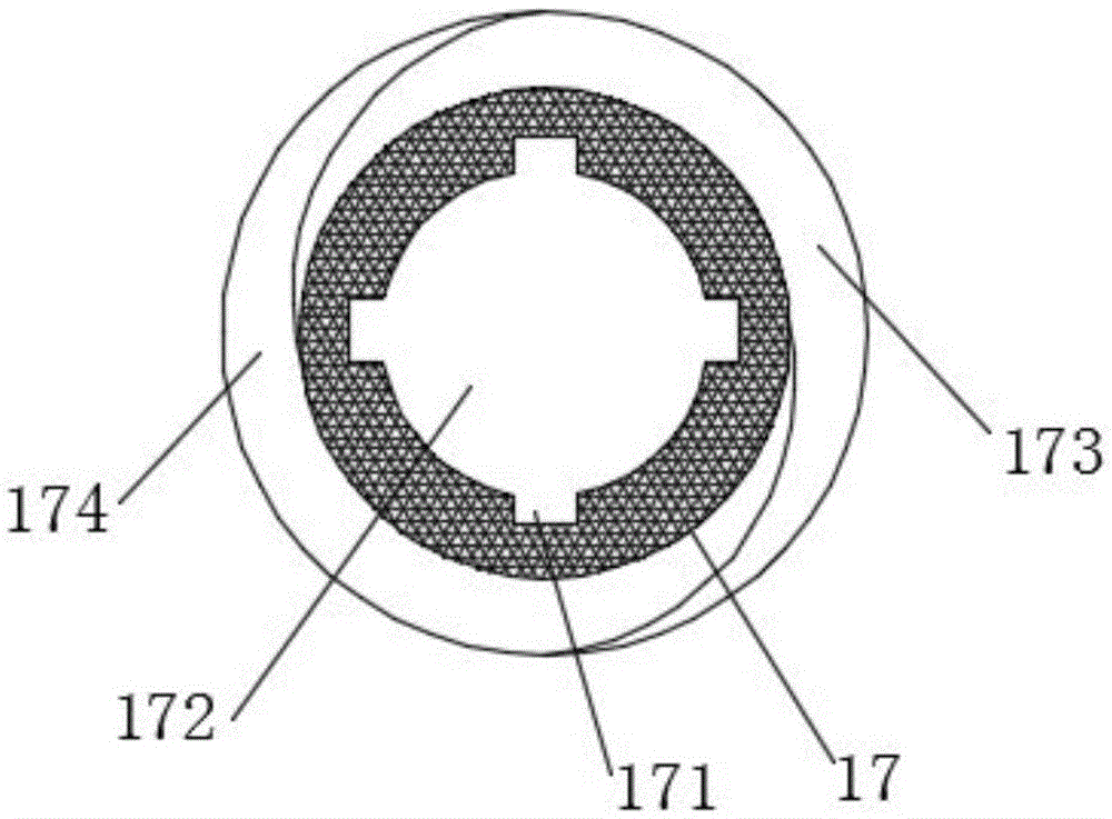
[0017] see Figure 1~4 , in an embodiment of the present invention, a PP plastic injection molding machine includes a feeding device, a machine barrel 12, a screw 13, a base 24, a motor 25, a metering device 28 and a machine head 29, and the feeding device includes a mixing bucket 1 and Feed hopper 9, the discharge opening of described mixing bucket 1 is arranged on the feed inlet of feeding hopper 9, and described mixing bucket 1 is inverted conical, and desc...


PUM


Abstract

The invention discloses a PP (Polypropylene) plastic injection molding machine. The PP plastic injection molding machine comprises a feeding device, a machine barrel, a screw rod, a base, a motor, a metering device and a machine head, wherein the feeding device comprises a stirring barrel and a feeding hopper; the stirring barrel is internally provided with a stirring device; an extruding screw rod is connected with the motor; the extruding screw rod comprises a core shaft, a locking nut, a flat gasket, a double-screw outer sleeve and a positioning key; double screws with the same lead are arranged outside the double-screw outer sleeve; a melt pump is arranged at a discharging end of the machine barrel; a filtering plate is arranged between the machine barrel and the melt pump; the melt pump is connected with the machine head; the metering device is arranged between the melt pump and the machine head; the machine head comprises a sleeve; a steel pipe, which is concentric with the sleeve, is arranged in the sleeve; an outer mold for extruding a material is arranged at one end of the sleeve; the steel pipe penetrates through the sleeve and the outer mold; a module sleeves outside a pipe body, located in the sleeve, of the steel pipe. The PP plastic injection molding machine is not easily blocked and the transferring amount of the injection molding machine is improved; the production efficiency is improved and the weight of a finished product can be accurately controlled.

Description

technical field [0001] The invention relates to an injection molding machine, in particular to a PP plastic injection molding machine. Background technique [0002] Injection molding machines are widely used in the production of plastics, rubber and other products. Plastic injection molding machine machinery has become one of the most widely used models in the plastic processing industry. The plastic injection molding machine can be matched with various plastic molding auxiliary machines such as pipe, film, handle material, monofilament, flat wire, packing belt, extruded net, plate, profile, granulation, cable coating, etc., to form a variety of plastic extrusion Molding production line, producing various plastic products. PP plastic particles are heated and fused in the barrel of the injection molding machine, and the heated plastic particles are in a glued state, and then extruded into the mold to cool and form. However, before the material enters the injection molding ...

Claims


Application Information

Patent Timeline
IPC IPC(8): B29C45/18B29C45/62B29C47/10B29C47/66
CPCB29C45/1808B29C45/62B29C48/286B29C48/681
Inventor 程树年
Owner 苏州乔布注塑工业有限公司
Learn More