
Workpiece clamping structure for grinding tool, and tracking type casting edging machine and method

A technology of workpiece clamping and grinding tools, which is applied in the direction of machine tools suitable for grinding workpiece edges, grinding workpiece supports, and grinding machine parts, etc. It can solve problems such as harsh working environment, complicated operation, and inability to adapt to small batch production.

Inactive Publication Date: 2016-05-25
UNIV OF JINAN
View PDF7 Cites 39 Cited by
  • Summary
  • Abstract
  • Description
  • Claims
  • Application Information

AI Technical Summary

Problems solved by technology

[0002] After casting, there will be problems such as flashes and burrs on the surface of castings. Most enterprises still use the traditional way of grinding hand-held castings on ordinary grinders (larger castings are ground with hand-held small grinding wheels). This working method causes labor intensity for workers. Large size, low production efficiency, harsh working environment, and uneven quality of finished products. At present, special grinding equipment, CNC machine tools and robot automatic grinding methods are used. Due to the complex shape of castings, small batches, many sizes and specifications, and large casting errors, the above The programming time of automatic grinding equipment is long, the operation is complicated, the production efficiency is low, and it does not meet the requirements of small batch production and castings with complex shapes. A grinding equipment that can quickly adapt to the shape and size of castings is needed

Method used


Image

  • Workpiece clamping structure for grinding tool, and tracking type casting edging machine and method
  • Workpiece clamping structure for grinding tool, and tracking type casting edging machine and method
  • Workpiece clamping structure for grinding tool, and tracking type casting edging machine and method

Examples


Embodiment Construction

[0049] The present invention will be further described below with reference to the embodiments of the present invention.

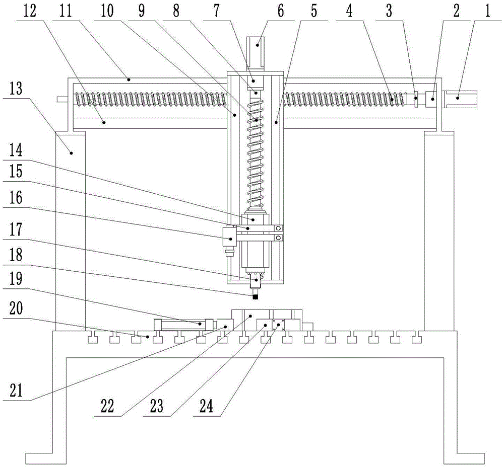
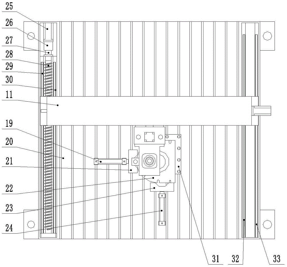
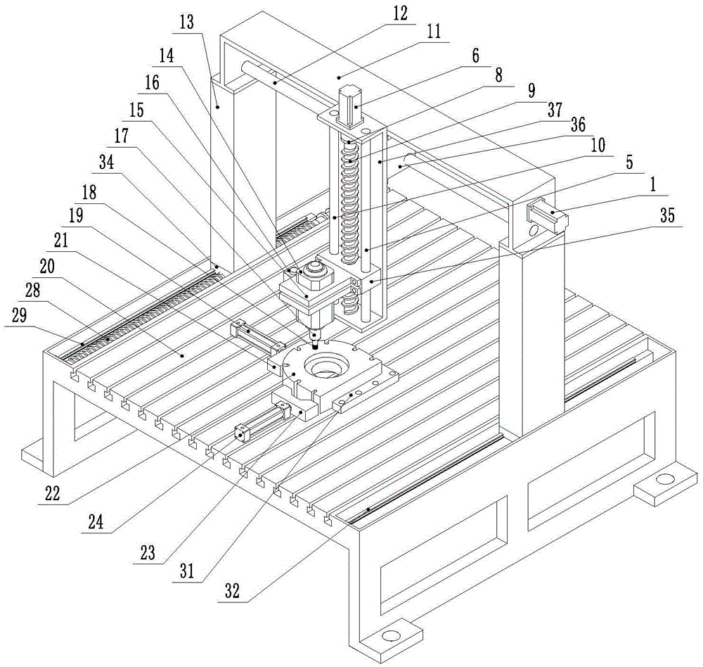
[0050] like Figure 1-3 As shown, a tracking type casting edging machine of the present invention includes an X-axis motor 1, an X-axis reducer 2, an X-axis coupling 3, an X-axis screw 4, a Z-axis right guide column 5, and a Z-axis motor 6. Z-axis reducer 7, Z-axis coupling 8, Z-axis screw 9, Z-axis left guide column 10, X-axis support 11, X-axis guide column 12, column 13, edging high-speed motor 14, Edging high-speed motor holder 15, industrial camera 16, grinding head quick change fixture 17, grinding head 18, X-direction cylinder 19, bed 20, X-direction clamping block 21, casting 22, edging groove 22-1, grinding Side outer circle 22-2, Y-direction clamping block 23, Y-direction cylinder 24, Y-axis motor 25, Y-axis reducer 26, Y-axis coupling 27, Y-axis screw 28, the first guide rail on the left side of the Y-axis 29. The second guide rail 30 on the l...


PUM


Abstract

The invention discloses a workpiece clamping structure for a grinding tool, and a tracking type casting edging machine and method. The workpiece clamping structure comprises a workbench, the workbench is provided with a plurality of positioning devices, at least one positioning device comprises a cylinder and a clamping block, and the clamping blocks clamp or leave a workpiece to be machined, under the action of cylinder piston rods. The tracking type casting edging machine comprises a bed, a moving mechanism, a grinding head assembly, the above-mentioned workpiece clamping structure, an industrial camera, a visual recognition system and a control system. The edging machine can quickly grind flash and burrs on a casting according to the requirements of a production drawing and the shape and size of the casting, without programming and equipment adjusting during casting replacement, the production efficiency is high, and machining error is small.

Description

technical field [0001] The invention relates to a workpiece clamping structure and a casting edging machine, in particular to a workpiece clamping structure for an abrasive tool and a tracking type casting edging machine. The invention also relates to a tracking type edging method of the tracking type casting edging machine. Background technique [0002] After casting, there will be flash, burr and other problems on the surface of the casting. Most enterprises still use the traditional hand-held casting method of grinding on an ordinary grinding machine (larger castings are ground with a small hand-held grinding wheel), which causes labor intensity of workers. Due to the complex shape of castings, small batches, many sizes and specifications, and large casting errors, the above-mentioned The automatic grinding equipment has long programming time, complicated operation and low production efficiency, and is not suitable for the requirements of small batch production and com...

Claims


Application Information

Patent Timeline
IPC IPC(8): B24B9/04B24B17/04B24B41/06B24B45/00B24B47/20B22D31/00
CPCB24B9/04B22D31/00B24B17/04B24B41/067B24B45/00B24B47/20
Inventor 李长春吴长忠陈乃建
Owner UNIV OF JINAN
Learn More