
Stamping die for automobile interior plates

A technology for stamping dies and plates, which is applied in the field of stamping dies for automotive inner panels, which can solve problems such as large punch vibration, worker fatigue, and reduced die life, and meet the requirements of reducing tonnage, less vibration of machine tools, and prolonging service life. Effect

Inactive Publication Date: 2016-05-25
TIANJIN BINHAI HIGH NEW DISTRICT WANGYUE TECH DEV CO LTD
View PDF7 Cites 4 Cited by
  • Summary
  • Abstract
  • Description
  • Claims
  • Application Information

AI Technical Summary

Problems solved by technology

The quality, production efficiency and production cost of stamping parts are directly related to the design and manufacture of the mold. Since all positions of the upper end surface of the die of the existing mold are at the same level, during stamping, all positions on the material to be punched out At the same time, force is applied. In this way, the tonnage of the punching machine is too high. At the same time, the punching machine vibrates too much and makes a lot of noise, which seriously affects the hearing of the workers, which is not good for the health of the workers, and easily leads to the fatigue of the workers.
In addition, the mold vibrates too much and has abnormal noise, which is easy to cause the punch and die to be bitten and damaged, which reduces the life of the mold

Method used


Image

  • Stamping die for automobile interior plates
  • Stamping die for automobile interior plates

Examples


Embodiment Construction

[0013] The following will clearly and completely describe the technical solutions in the embodiments of the present invention with reference to the accompanying drawings in the embodiments of the present invention. Obviously, the described embodiments are only some, not all, embodiments of the present invention.

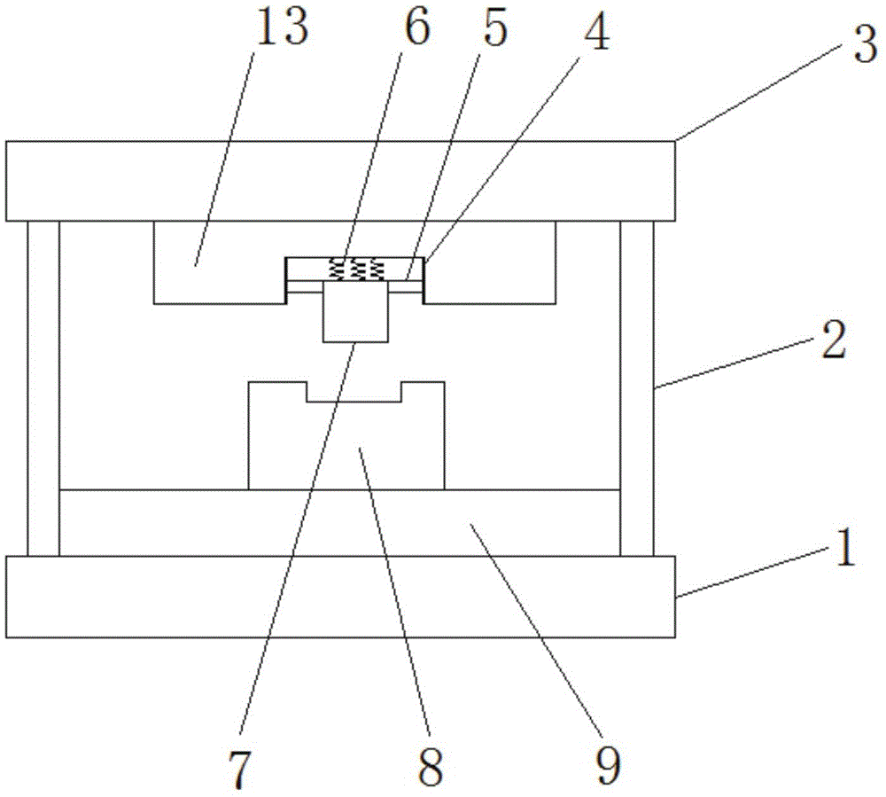
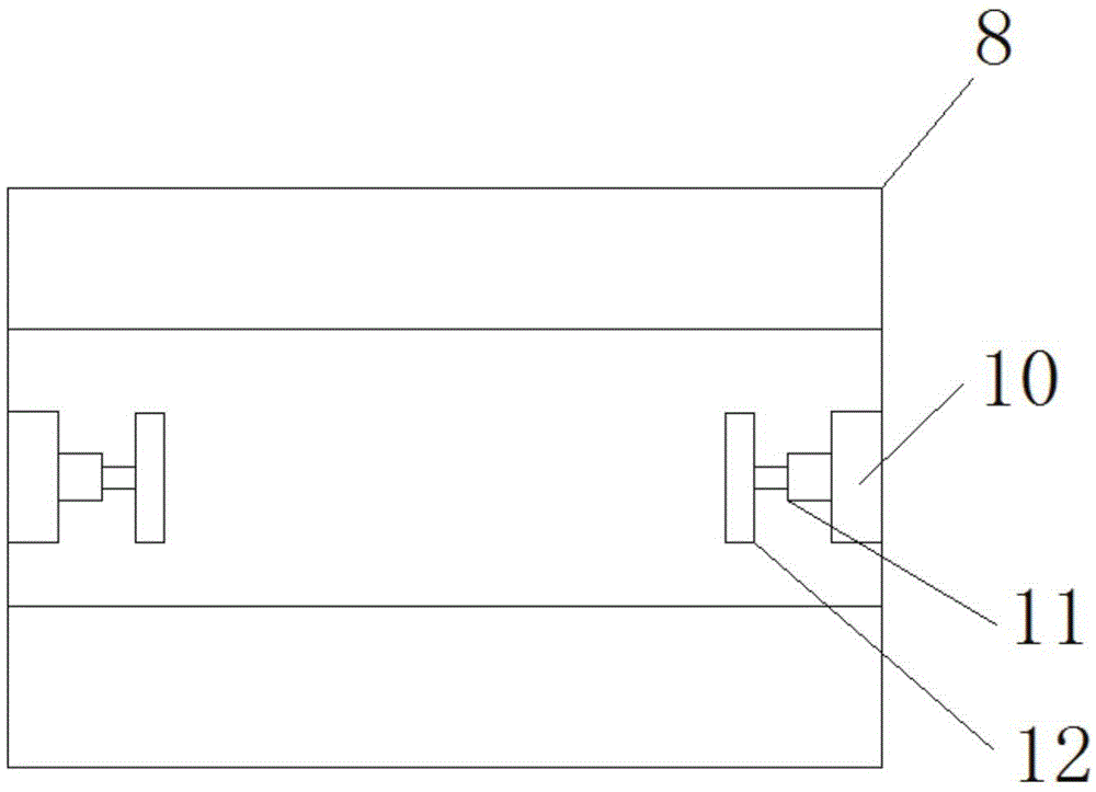
[0014] refer to Figure 1-2 , a stamping die for an automobile inner panel, comprising a lower die base 1, a plurality of support rods 2 are arranged on the upper end of the lower die base 1, and an upper die base 3 is arranged on the upper end of the support rods 2 away from the lower die base 1, and the upper die base 3 One side near the lower mold base 1 is provided with a first fixing seat 13, and the first fixing base 13 is located between a plurality of support rods 2, and the first fixing base 13 is provided with a slot near the side of the lower mold base 1, and the opening There are vertically arranged slide rails 4 on the inner wall of the tank, a connectin...


PUM


Abstract

The invention discloses a stamping die for automobile interior plates. The stamping die comprises a lower die base. A plurality of supporting rods are arranged at the upper end of the lower die base. An upper die base is arranged at the upper ends, away from the lower die base, of the supporting rods. A first fixing base is arranged on the side, close to the lower die base, of the upper die base. A notch is formed in the side, close to the lower die base, of the first fixing base. Sliding rails are symmetrically arranged on the inner wall of the notch and vertically arrayed. A connecting block is arranged between the two sliding rails. A male die is arranged on the connecting block. A plurality of springs are arranged on the side, close to the upper die base, of the male die at equal intervals. A second fixing base is arranged at the upper end of the lower die base and located among the supporting rods. The stamping die is simple in structure, greatly lowers the requirement for the tonnage of a machine tool and reduces cost; besides, the machine tool hardly vibrates, and thus noise is reduced; the stamping die hardly vibrates and does not generate abnormal sounds, the service life of the male die and a female die is prolonged, the quality of the stamping die is improved, and manpower and material resources are saved.

Description

technical field [0001] The invention relates to the technical field of stamping dies, in particular to a stamping die for an automobile inner panel. Background technique [0002] Stamping die is a special process equipment for processing materials (metal or non-metal) into parts (or semi-finished products) in cold stamping processing, called cold stamping die (commonly known as cold stamping die). Stamping is a pressure processing method that uses a mold installed on a press to apply pressure to the material at room temperature to cause separation or plastic deformation to obtain the required parts. Stamping molds are essential process equipment for stamping production , is a technology-intensive product. The quality, production efficiency and production cost of stamping parts are directly related to the design and manufacture of the mold. Since all positions of the upper end surface of the die of the existing mold are at the same level, during stamping, all positions on th...

Claims


Application Information

Patent Timeline
IPC IPC(8): B21D37/10B21D37/12B21D43/00B26F1/44
CPCB21D37/10B21D37/12B21D43/003B26F1/44B26F2001/4409
Inventor 高彩超
Owner TIANJIN BINHAI HIGH NEW DISTRICT WANGYUE TECH DEV CO LTD
Learn More