Dry and wet coupling electrostatic dust collection system and dust collection technology

A dry-wet coupling, electrostatic dust removal technology, applied in the direction of electrostatic separation, electrostatic effect separation, electrode structure, etc., can solve the problems of ultra-clean emission of flue gas particles, the inability of ultra-clean emission of particulate matter, and the reduction of flue gas temperature. The effect of small amount of engineering, ultra-clean emission, and avoiding condensation

Inactive Publication Date: 2016-05-18
CHNA ENERGY INVESTMENT CORP LTD +3
View PDF6 Cites 1 Cited by
  • Summary
  • Abstract
  • Description
  • Claims
  • Application Information

AI Technical Summary

Problems solved by technology

However, for coal-fired units that adopt in-furnace desulfurization or in-furnace desulfurization + semi-dry desulfurization outside the furnace, and use electrostatic precipitators or bag filter dust removal at the end, it is very difficult to achieve ultra-clean emission of final flue gas particles
In recent years, for the reduction of particulate matter in the above-mentioned types of coal-fired units, attempts have been made to increase the removal efficiency by increasing the number of electric fields, changing the electric bag compound, changing the final electric field to a rotating electrode, and changing the high-frequency power supply. However, it can be seen from actual engineering examples On the one hand, the cost of transformation is huge, on the other hand, the emission of particulate matter still cannot meet the requirements of ultra-cleanness, and the temperature of flue gas is excessively reduced during the cleaning process, which is not conducive to subsequent energy utilization. This has become an urgent problem for the industry to solve

Method used


Image

  • Dry and wet coupling electrostatic dust collection system and dust collection technology
  • Dry and wet coupling electrostatic dust collection system and dust collection technology

Examples


Embodiment Construction

[0032] The technical solutions in the embodiments of the present invention will be clearly and completely described below in conjunction with the drawings in the embodiments of the present invention.

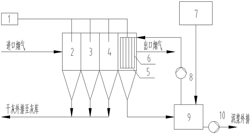
[0033] Taking the 150MW circulating fluidized bed coal-fired power generation unit as an example, the flue gas desulfurization process is furnace desulfurization. The original dust removal system uses a 4-field electrostatic precipitator. The inlet flue gas temperature of the dust collector is 120°C, and the inlet particle concentration is 6600mg / m 3 , outlet particle concentration 20mg / m 3 , the dust collector plate of the fourth electric field is now replaced with a wet flexible plate 6, while the first electric field 2, the second electric field 3, the third electric field 4, the fourth electric field 5, the DC high voltage power supply 1 and the shell of the dust collector are all remain unchanged, as in figure 1 and 2 shown. The supernatant produced by the horizontal cen...


PUM


Abstract

The invention discloses a dry and wet coupling electrostatic dust collection system and a dust collection technology. Multiple stages of electric fields are arranged in the dry and wet coupling electrostatic dust collection system. A dust collection plate in the last stage of electric field is a wet type pole plate. A plurality of rows of transverse water distributing pipes which are perpendicular to the wet type pole plate or inclined relative to the wet type pole plate are arranged above the wet type pole plate. A plurality of water distributing micro-holes are formed in each row of transverse water distributing pipe. The bottom of the last stage of electric field is connected with an ash sluicing water treatment recycling system through a water collection device. A centrifugal machine or a flocculent precipitating tank is connected with the transverse water distributing pipes through a water inlet pipe to achieve water resource recycling. The dry and wet coupling electrostatic dust collection system and the dust collection technology have the beneficial effects that the requirements for the smoke temperature, the flow speed, the operation voltage and the like of the electric field where the wet type pole plate is located are matched with those of the electric field at the front end of the wet type pole plate, so that in the practical transformation process, a shell of an original electrostatic dust collector can be reserved, transformation can be completed under the assistance of a flushing water system, the transformation project amount is small, and cost is low. A water distributing system is designed and matched with the flexible pole plate, so that water does not make direct contact with smoke, the influence on temperature reduction of the smoke is very low, smoke condensation is avoided, and meanwhile damage to subsequent equipment is avoided.

Description

technical field [0001] The invention relates to the technical field of flue gas purification and environmental protection equipment, in particular to a dry-wet coupling electrostatic dust removal system and a dust removal process. Background technique [0002] On December 2, 2015, the executive meeting of the State Council decided that coal-fired power plants should comprehensively implement ultra-low emission and energy-saving renovations, significantly reducing coal consumption and pollution emissions for power generation. The "Coal Power Energy Conservation and Emission Reduction Upgrading and Transformation Action Plan (2014-2020)" released in 2014 stipulated that by the end of 2020, the ultra-clean emission transformation in the eastern region should be completed. The resolution of the executive meeting of the State Council shows that the state's governance of coal-fired flue gas has far exceeded expectations. [0003] As far as the emission of particulate matter is co...

Claims


Application Information

Patent Timeline
IPC IPC(8): B03C3/00B03C3/34B03C3/53
CPCB03C3/00B03C3/34B03C3/53
Inventor 常景彩武锡平张波张梦泽郇庆超
Owner CHNA ENERGY INVESTMENT CORP LTD
Why Eureka
Try Eureka