
Chip packaging method and packaging assembly

A packaging component and chip packaging technology, which is applied in the field of semiconductors, can solve problems such as pin layout restrictions and electrical performance degradation, and achieve the effect of low packaging resistance and flexible design

Inactive Publication Date: 2016-05-11
HEFEI SMAT TECH CO LTD
View PDF11 Cites 17 Cited by
  • Summary
  • Abstract
  • Description
  • Claims
  • Application Information

AI Technical Summary

Problems solved by technology

[0007] In view of this, the object of the present invention is to provide a method to replace the lead frame and the bonding wire by using the redistribution layer, so as to solve the problem that the bonding wire causes the electrical performance to deteriorate and the lead frame causes pin layout restrictions.

Method used


Image

  • Chip packaging method and packaging assembly
  • Chip packaging method and packaging assembly
  • Chip packaging method and packaging assembly

Examples


Embodiment Construction

[0042] The present invention will be described in more detail below with reference to the accompanying drawings. In the various figures, like elements are designated by like reference numerals. For the sake of clarity, various parts in the figures have not been drawn to scale. Additionally, some well-known parts may not be shown. For the sake of simplicity, the semiconductor structure obtained after several steps can be depicted in one figure.

[0043] It will be understood that, in describing the structure of a device, when a layer or region is referred to as being "on" or "over" another layer or region, it can be directly on the other layer or region, or Other layers or regions are also included between it and another layer, another region. And, if the device is turned over, the layer, one region, will be "under" or "under" another layer, another region.

[0044] In order to describe the situation directly above another layer, another area, the expression "A is directly ab...


PUM


Abstract

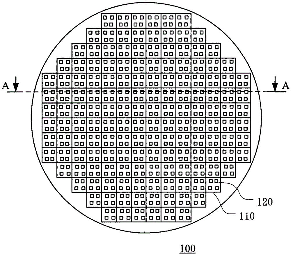
The invention discloses a chip packaging method and a packaging assembly. The chip packaging method comprises the steps of forming a first packaging layer on multiple chips, wherein the multiple chips comprise opposite first surfaces and second surfaces respectively, and multiple first conductive convex blocks formed on the first surfaces; forming a re-wiring layer on the surface of the first packaging layer; forming multiple second conductive convex blocks on the re-wiring layer so as to form the packaging structure; and separating the packaging structure into multiple packaging assemblies, wherein the re-wiring layer enables the multiple first conductive convex blocks to be connected to the multiple second conductive convex blocks so as to provide a conductive path from the multiple chips to an external circuit. According to the chip packaging method, a lead frame and a bonding wire can be saved, so that flexible pin layout is allowed, and the electrical performance of the packaging assemblies is improved.

Description

technical field [0001] The present invention relates to semiconductor technology, and more particularly, to a wafer-level chip packaging method and package assembly that do not require a lead frame. Background technique [0002] Chip encapsulation is the process of encapsulating a chip in an encapsulant, thereby isolating the semiconductor material from the external environment and providing electrical connection to external circuits. The package assembly formed after the chip packaging process is a chip product that can be sold in the market. [0003] The existing chip packaging process includes multiple steps such as dicing the wafer into individual chips, placing the individual chips on the lead frame, plastic encapsulation and cutting the lead frame. A further improved chip packaging process involves placing leadframes and molding over the entire wafer, and then dicing the wafer, molding compound, and leadframe together into individual package components. This improved...

Claims


Application Information

Patent Timeline
IPC IPC(8): H01L21/56H01L21/60H01L23/31H01L23/48
CPCH01L2224/04105H01L2224/12105H01L2224/73267H01L2224/94H01L2924/18162H01L2924/3512H01L2224/27H01L24/81H01L21/56H01L23/3107H01L23/48
Inventor 尤文胜
Owner HEFEI SMAT TECH CO LTD
Learn More