
Bionic cable

A technology for cables and oil pipes, applied to cables. It can solve the problem that the insulating oil cannot flow down the oil pipe

Inactive Publication Date: 2016-05-11
深圳市禾力科技股份有限公司
View PDF3 Cites 1 Cited by
  • Summary
  • Abstract
  • Description
  • Claims
  • Application Information

AI Technical Summary

Problems solved by technology

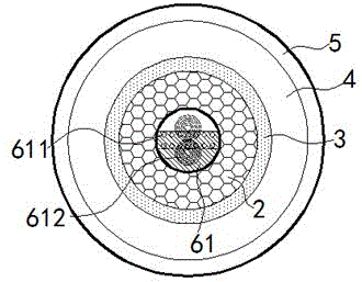
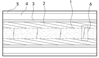
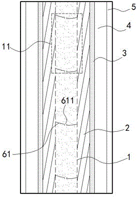
[0005] The beneficial effects of the present invention are: the bionic cable is laid according to the circuit planning diagram, the insulating oil in each oil section flows to the wire layer through the diversion hole, and the insulating oil fills the cable through the capillary holes in the cable; according to the principle of capillary phenomenon , under the effect of surface tension, the insulating oil will not overflow downward under the action of gravity after filling the cable; since the insulating oil is always subject to the vertical downward force of gravity, the disconnectors located in the horizontal oil pipe are not affected Under the action of external force, each pair of shrapnel on each of the isolators remains parallel and there is a gap, so the oil sections are connected to each other; in the vertical section of the cable, each of the isolators is pressed by the gravity of the insulating oil above, and the spacers of the isolators A pair of shrapnels are slightly deformed and close to each other. At this time, the flow-restricting holes on the shrapnels are blocked, and the vertical sections of the oil pipe are separated into independent closed oil sections. The insulating oil in each oil section cannot flow along the oil pipe. Therefore, even if there is a large height difference in the cable, the oil section on the cable will not leak oil, dry up, etc.; therefore, the present invention effectively solves the problem of height difference limitation of the traditional oil-filled cable, making the oil-filled cable can be applied more widely

Method used


Image

  • Bionic cable
  • Bionic cable
  • Bionic cable

Examples


Embodiment

[0015] exist Figure 1 to Figure 3 In the shown embodiment, the bionic cable includes an oil pipe 1, a wire layer 2, a shielding layer 3, an insulating layer 4 and a housing 5 from the inside to the outside, and the oil pipe 1 communicates with the supplementary oil tank; and supplementary oil tank is filled with insulating oil; the oil pipe 1 is made of insulating material, and a diversion hole is opened on the pipe wall of the oil pipe 1; an isolator is installed equidistantly in the axial direction inside the oil pipe 1 6, such as figure 2 Shown in the dotted line box in the middle; each said cut-off device 6 divides said oil pipe 1 into oil sections 11 of equal length, as image 3 Shown in the dotted line box in the middle; the partition 6 includes a pair of shrapnel 61 parallel to each other, stacked and perpendicular to the axis of the oil pipe 1, and the length of the shrapnel 61 is 0.6-0.8 times the diameter of the oil pipe 1; the shrapnel 61 The fixed end is instal...


PUM


Abstract

The invention relates to a bionic cable. The bionic cable comprises an oil tube, a conductive wire layer, a shielding layer, an insulating layer and a shell which are arranged from inside to outside. The oil tube is communicated with a supplementing oil tank. The oil tube and the supplementing oil tank are internally filled with insulating oil. The oil tube is made of insulating material. The tube wall of the oil tube is provided with flow guide holes. Separators are equidistantly installed in the axial direction in the oil tube. The oil tube is separated into oil segments of equal length by all the separators. Each separator comprises a pair of elastic sheets which are laminated in parallel and perpendicular to the axis of the oil tube. The fixing ends of the elastic sheets are installed on the tube wall of the oil tube, and the flexible ends of the elastic sheets are provided with flow-limiting holes. The flow-limiting hole of one elastic sheet of the same pair of elastic sheets is shielded by the adjacent elastic sheet under the natural state. According to the bionic cable, the restriction of height difference can be eliminated, range of application of an oil-filled cable can be expanded, and installation complexity of the cable can also be simplified.

Description

technical field [0001] The present invention relates to a power line, in particular to a cable. Background technique [0002] The shape of the cable is similar to a rope, usually twisted and wound by multiple or multiple groups of wires, each group of wires is insulated from each other, twisted around a center, and wrapped with an insulating shell on the outside; tightly fitted wires Capillary tubes are formed between them; in order to ensure the normal and stable operation of the cable, insulating oil is often filled in the cable, and the insulating oil flows in the capillary tube and fills the entire cable; the insulating oil can effectively eliminate the change of load in the insulating layer. The resulting air gap improves the working field strength of the cable; the oil passage of the traditional oil-filled cable is integrally connected. When there is a large height difference between the two ends of the cable, the insulating oil in the oil passage will flow downward ...

Claims


Application Information

Patent Timeline
Patent Type & Authority Applications(China)
IPC IPC(8): H01B9/06H01B7/02
Inventor 顾钰锋
Owner 深圳市禾力科技股份有限公司
Learn More