
Full-automatic assembling equipment

An assembly equipment and fully automatic technology, applied in the field of mechanical equipment, can solve problems such as low efficiency, automatic processing without equipment, manual processing, etc., and achieve the effect of improving processing efficiency

Active Publication Date: 2016-05-11
NINGBO DAZHENG IND ROBOT TECH CORP
View PDF8 Cites 6 Cited by
  • Summary
  • Abstract
  • Description
  • Claims
  • Application Information

AI Technical Summary

Problems solved by technology

[0002] With the development of mechanical automation, more and more automation equipment can meet people's production needs, but the general production of automation equipment is aimed at the production and processing of some relatively common standard workpieces, and it is difficult to pass simple Resetting or modification to meet the processing needs of new workpieces
For example, in production practice, a workpiece needs to be assembled and processed. This workpiece is assembled from three parts. It is not a universal workpiece, so there is no ready-made equipment to realize its automatic processing. It can only be processed manually, which is inefficient
For example, in the patent application "Automatic Processing Equipment for Copper Pipe Connectors" with publication number CN105058147A, this equipment can only realize specific processing operations for copper pipe connectors, and cannot meet the needs of special workpieces to be processed.

Method used


Image

  • Full-automatic assembling equipment
  • Full-automatic assembling equipment
  • Full-automatic assembling equipment

Examples


Embodiment Construction

[0030] The present invention will be further described in detail below in conjunction with the accompanying drawings and specific embodiments. It should be noted that, in the case of no conflict, the embodiments of the present application and the features in the embodiments can be combined with each other.

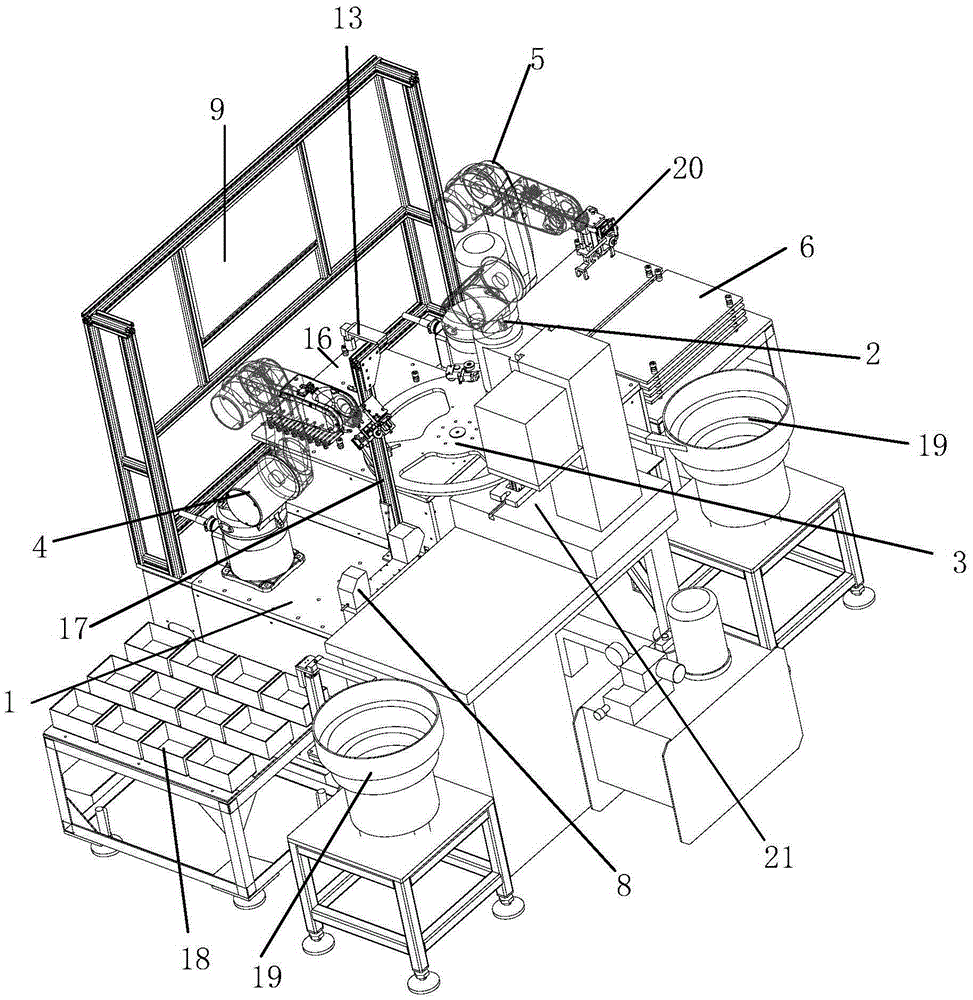
[0031] Such as Figure 1 to Figure 4 As shown, the fully automatic assembly equipment according to the embodiment of the present invention includes a mounting base 1 and a workbench 3 installed on the mounting base 1, a processing device 2, a first robot 4, and a second robot 5, wherein:

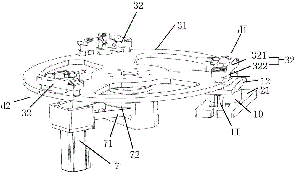
[0032] The workbench 3 includes a turntable 31 and a driving device, the drive device is used to drive the turntable 31 to rotate, and the turntable 31 is evenly equipped with three processing tools 32 that cooperate with the processing equipment 2, when one of them When the processing tool 32 is rotated to the processing position 21 of the processing equipment 2, the other two processi...


PUM


Abstract

The invention provides full-automatic assembling equipment which comprises an installing base, a working table, machining equipment, a first robot and a second robot. The working table, the machining equipment, the first robot and the second robot are installed on the installing base. The working table comprises a rotary disc and a drive device. Three machining tools fitted with the machining equipment are installed on the rotary disc uniformly. A machining position, an operation position of the first robot and an operation position of the second robot are sequentially distributed in the rotating direction of the rotary disc. The first robot is used for taking out finished products on the machining tool located at the operation position of the first robot and placing parts on the machining tool. The second robot is used for placing the parts on the machining tool at the operation position of the second robot. The machining equipment is used for machining the parts in the machining tool at the machining position into the finished products. The full-automatic assembling equipment can automatically machine workpieces needing to be machined, so that production efficiency is improved.

Description

technical field [0001] The invention relates to the field of mechanical equipment, in particular to a fully automatic assembly equipment. Background technique [0002] With the development of mechanical automation, more and more automation equipment can meet people's production needs, but the general production of automation equipment is aimed at the production and processing of some relatively common standard workpieces, and it is difficult to pass simple Resetting or refitting to meet the processing needs of new workpieces. For example, in production practice, a workpiece needs to be assembled and processed. This workpiece is assembled from three parts. It is not a universal workpiece, so there is no ready-made equipment to realize its automatic processing. It can only be processed manually, which is inefficient . For example, in the patent application "Automatic Processing Equipment for Copper Pipe Connectors" with publication number CN105058147A, this equipment can onl...

Claims


Application Information

Patent Timeline
Patent Type & Authority Applications(China)
IPC IPC(8): B23P21/00
CPCB23P21/006
Inventor 戴翔
Owner NINGBO DAZHENG IND ROBOT TECH CORP
Learn More