
Hydraulic gear grinding clamp capable of rapidly replacing large-size workpieces and clamping method of hydraulic gear grinding clamp

A large-scale, workpiece technology, applied in the field of large-scale disc-shaped cylindrical gear grinding fixtures, to achieve the effect of flexible movement, meeting the needs of batch processing, and high positioning accuracy

Active Publication Date: 2016-05-11
秦川机床工具集团股份公司
View PDF5 Cites 11 Cited by
  • Summary
  • Abstract
  • Description
  • Claims
  • Application Information

AI Technical Summary

Problems solved by technology

[0004] The purpose of the present invention is to solve the problem of fast and accurate automatic clamping in the batch processing of large-scale disc gears, and to provide a hydraulic gear grinding fixture and its clamping method that can quickly replace large-scale workpieces (such as disc gears)

Method used


Image

  • Hydraulic gear grinding clamp capable of rapidly replacing large-size workpieces and clamping method of hydraulic gear grinding clamp
  • Hydraulic gear grinding clamp capable of rapidly replacing large-size workpieces and clamping method of hydraulic gear grinding clamp

Examples


Embodiment Construction

[0022] The present invention will be described in detail below in conjunction with the accompanying drawings and embodiments.

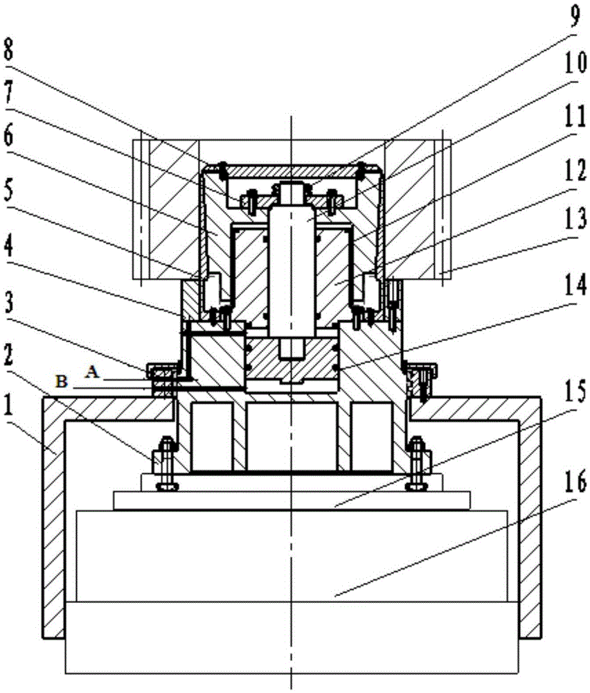
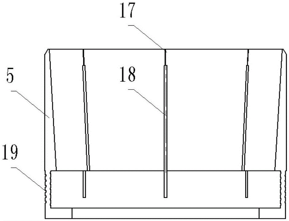
[0023] see figure 1 , the hydraulic gear grinding fixture that can quickly replace large-sized workpieces according to the present invention includes a bracket 1, an oil cylinder base 2, a slip ring 3, a support ring 4, an elastic expansion sleeve 5, a tapered mandrel 6, a connecting plate 7, and an end cover 8. Round nut 9, connecting shaft 10, dense bead guide sleeve 11, centering seat 12 and piston 14. The support 1 is installed on the workbench base 16, the oil cylinder base 2 is installed and fixed on the rotating table 15, the rotating table 15 is supported on the workbench base 16, and the rotating table 15 can drive the oil cylinder base 12 to rotate. The piston 14 is installed in the oil cylinder base 2, the centering seat 12 is installed and fixed on the upper end of the oil cylinder base 2, the connecting shaft 10 is arranged on the hollow...


PUM


Abstract

The invention provides a hydraulic gear grinding clamp capable of rapidly replacing large-size workpieces and a clamping method of the hydraulic gear grinding clamp. The hydraulic gear grinding clamp comprises an oil cylinder base, a sliding ring, a supporting ring, an elastic expanding sleeve, a conical central spindle, a connecting plate, a connecting shaft, a dense ball guiding sleeve, a centering seat and a piston. The oil cylinder base is mounted on a rotary table surface. The sliding ring and the oil cylinder base form two independently sealed annular oil cavities by being matched in the radial direction, and the oil cavities correspond to oil inlets A and B respectively. Oil channels are formed in the oil cylinder base, correspond to the oil inlets A and B respectively and lead to an upper oil cavity and a lower oil cavity of the piston respectively. The conical central spindle is connected with the piston into a whole through the connecting plate and the connecting shaft. The dense ball guiding sleeve is mounted between the centering seat and the conical central spindle. The elastic expanding sleeve is mounted by being coaxial with the conical central spindle and fixed to the upper end of the oil cylinder base. According to the hydraulic gear grinding clamp capable of rapidly replacing the large-size workpieces and the clamping method of the hydraulic gear grinding clamp, hydraulic oil drives the piston to drive the conical central spindle to squeeze and loosen the elastic expanding sleeve so as to achieve clamping and loosening actions of the workpieces, large-size gears can be rapidly and automatically clamped, the machining efficiency is improved, and the automation level of a machine tool is raised.

Description

technical field [0001] The invention relates to a gear grinding fixture for a gear grinding machine, in particular to a gear grinding fixture for a large-sized disc-shaped cylindrical gear. Background technique [0002] The rapid development of industries such as wind power, marine equipment, and military industry requires a large number of large-scale, high-precision hardened gears. For gears with the same specification and large batches, in order to improve the processing efficiency, in addition to using high-efficiency machine tools, it is necessary to be equipped with grinding fixtures that can quickly replace and clamp the gears. [0003] The current gear grinding fixtures mostly use manual positioning and clamping. On the one hand, the clamping force relies on manual adjustment, which is highly random, and it is difficult to ensure reliable clamping of large-sized workpieces; Requirements for mass processing of specification gears. At the same time, the clamping elem...

Claims


Application Information

Patent Timeline
Patent Type & Authority Applications(China)
IPC IPC(8): B23F23/06
CPCB23F23/06
Inventor 郭召
Owner 秦川机床工具集团股份公司
Learn More