Apparatus for obtaining high-quality optical images in a magnetic resonance imaging system

A nuclear magnetic resonance imaging and optical sensing technology, applied in the field of medical imaging, can solve problems such as interfering with the workflow, and achieve the effect of low heat dissipation and drift prevention

Active Publication Date: 2016-05-04
THE BOARD OF TRUSTEES OF THE LELAND STANFORD JUNIOR UNIV
View PDF9 Cites 2 Cited by
  • Summary
  • Abstract
  • Description
  • Claims
  • Application Information

AI Technical Summary

Problems solved by technology

These issues have been a hindrance to the technology's adoption as a conventional coffin tool because they interfere with workflow

Method used


Image

  • Apparatus for obtaining high-quality optical images in a magnetic resonance imaging system
  • Apparatus for obtaining high-quality optical images in a magnetic resonance imaging system
  • Apparatus for obtaining high-quality optical images in a magnetic resonance imaging system

Examples


Embodiment Construction

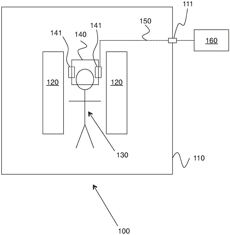
[0022] figure 1 An exemplary device based on the above principles is shown. Apparatus 100 includes a Faraday cage 110 that surrounds an MRI machine 120 within which a person (or animal) 130 is placed. The human head or animal is partially surrounded by an imaging coil 140 comprising one or more integrated cameras 141 . The only data communication with camera 141 is via optical fiber 150 , which passes through the Faraday cage to processing device 160 via waveguide 111 .

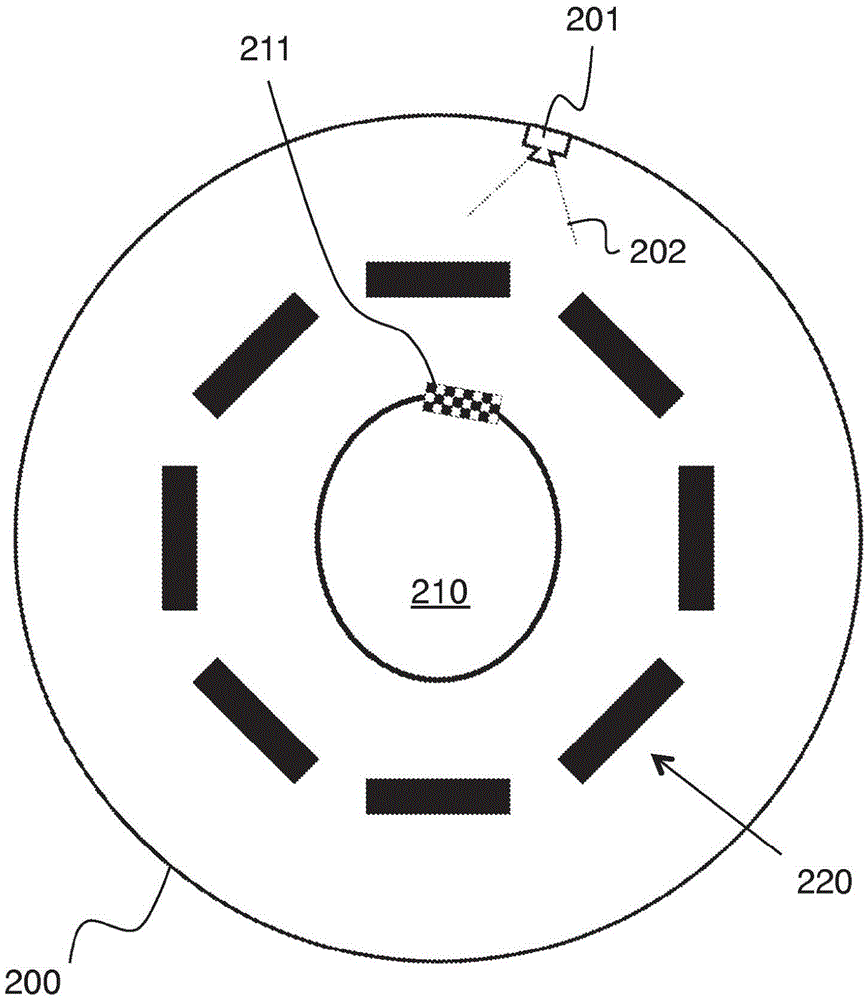
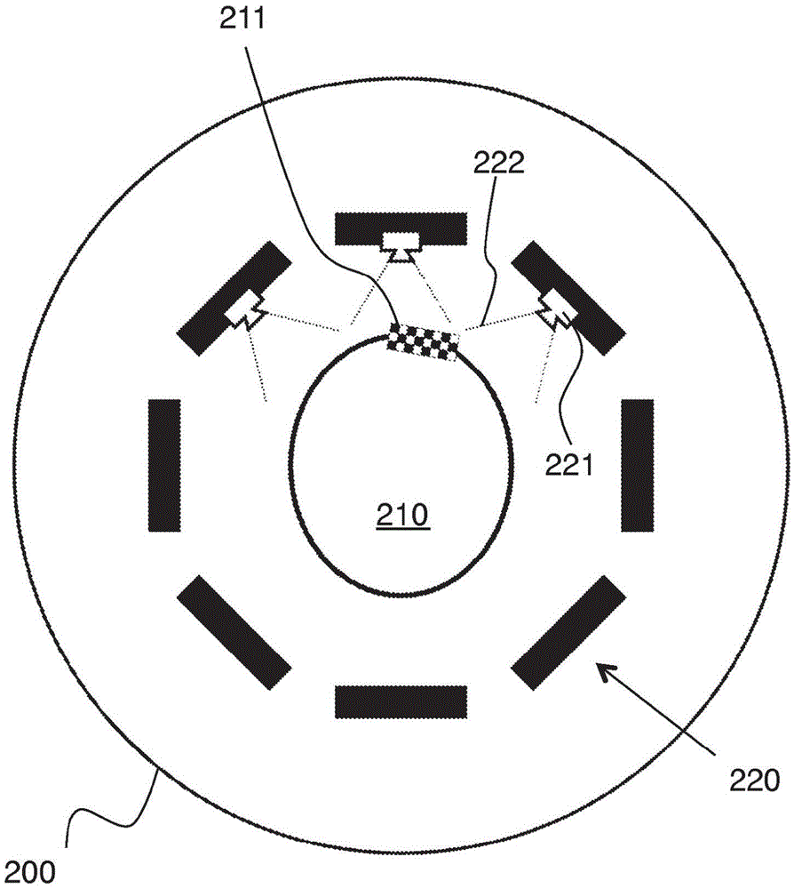
[0023] In order to better understand the present invention, it is helpful to consider the disadvantages of hole-mounted cameras. Figure 2A An MRI scanner bore 200 is shown surrounding a patient's head 210 with attached tracking markers 211 . As can be seen from the diagram, aperture mounted camera 201 suffers from the drawback that its field of view 202 will be significantly blocked by head coil 220 .

[0024] Figure 2B A similar arrangement is shown, except that a camera 221 is positioned on (or prefe...


PUM


Abstract

A miniature, low-power, optical sensing device that operates in the harsh electromagnetic environment of a magnetic resonance imaging system is provided. The device includes a means of transferring imaging data obtained with the optical sensor out of this harsh electromagnetic environment without requiring a galvanic connection. It is practical to power the device using a small battery that is compatible with the harsh environment. In other embodiments, the device is powered using 'power over fiber' or by taking power by power harvesting directly from the harsh electromagnetic environment. One embodiment is to directly integrate the device into a magnetic resonance imaging (MRI) head coil, using a wired connection to the head coil to provide electrical power. Here the wired connection does not penetrate the Faraday cage of the MRI system or cross into the bore of the MRI system from outside the bore.

Description

field of invention [0001] The present invention relates to medical imaging. In particular, the present invention relates to devices for obtaining high quality optical data from human or animal subjects during simultaneous magnetic resonance imaging. Background technique [0002] Magnetic resonance imaging (MRI) is an invaluable tool in clinical imaging. MRI uses a strong static magnetic field (B0), a strong radio frequency (RF) field (B1), and rapidly switching magnetic field gradients to generate spatially encoded signals. Due to these magnetic fields, patient detection during MRI can be challenging because it is difficult to operate electronics in this environment. The static magnetic fields used are typically between 1.5T and 7T, which precludes the use of ferromagnetic materials in any electronics placed within the scanning aperture. The RF field is a source of electromagnetic interference and the gradient field is a source of mechanical vibration (of conductive mater...

Claims


Application Information

Patent Timeline
Patent Type & Authority Applications(China)
IPC IPC(8): A61B5/055
CPCA61B5/055A61B5/721A61B5/0077G01R33/283G01R33/34046A61B2090/306A61B2090/3937A61B3/112A61B3/113A61B5/0013A61B5/0035A61B5/0059A61B5/02055A61B5/02416A61B5/08A61B2562/0233G01R33/4808G01R33/56509
Inventor R·巴马M·阿克索耶J·马克拉伦
Owner THE BOARD OF TRUSTEES OF THE LELAND STANFORD JUNIOR UNIV
Why Eureka
Try Eureka