
Constant current driving system and constant current driving method for stepping motor with fixed duty ratio

A technology of stepping motor and fixed duty, applied in the control system, motor generator control, electrical components, etc., can solve the problems of poor portability and scalability, complex hardware circuit structure, poor software flexibility, etc., to reduce software Hardware design complexity, simplified software design, and the effect of simplified software and hardware design

Active Publication Date: 2016-05-04
XIAN AVIATION COMPUTING TECH RES INST OF AVIATION IND CORP OF CHINA
View PDF4 Cites 6 Cited by
  • Summary
  • Abstract
  • Description
  • Claims
  • Application Information

AI Technical Summary

Problems solved by technology

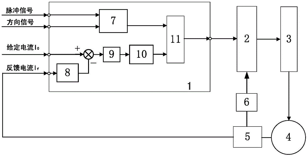
[0017] 1. Most of them are implemented by analog or digital circuits, and A / D conversion chips are needed to collect the motor winding current, and the hardware circuit structure is complex;
[0018] 2. In the control of each shot, the PWM duty cycle needs to be calculated in real time according to the magnitude of the feedback current. The software has poor flexibility, high complexity, poor portability and scalability

Method used


Image

  • Constant current driving system and constant current driving method for stepping motor with fixed duty ratio
  • Constant current driving system and constant current driving method for stepping motor with fixed duty ratio
  • Constant current driving system and constant current driving method for stepping motor with fixed duty ratio

Examples


Embodiment Construction

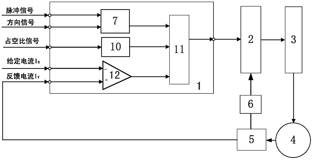
[0039] image 3 Shown is the block diagram of the constant current drive structure of the stepper motor of the present invention, a constant current drive system of the stepper motor with a fixed duty ratio of the present invention, including a control unit 1, a drive circuit 2, a power circuit 3, a stepper motor 4, a current Sensor 5, protection circuit 6; Control unit includes pulse divider 7, PWM generator 10 and logic operator 11; The improvement of this system is: control unit also includes comparator 12, and described comparator includes input positive terminal, Input the negative terminal and the output terminal, the input negative terminal is used to input the given value of the motor winding current, the input positive terminal is connected to the current sensor to receive the feedback value of the motor winding current; the output terminal is connected to the logic operator;

[0040] The system uses a comparison unit to replace the A / D conversion and PID solver or hy...


PUM


Abstract

The invention relates to the technical field of motor control, and particularly relates to a constant current driving system and a constant current driving method for a stepping motor with a fixed duty ratio. The system comprises a control unit, a driving circuit, a power circuit, a stepping motor, a current sensor and a protection circuit, wherein the control unit comprises a pulse distributor, a PWM generator and a logic arithmetic unit. The system is characterized in that the control unit also comprises a comparator, wherein the comparator, comprises an input positive end, an input negative end and an output end; the input negative end is connected with a stepping motor winding current given value; the input positive end is connected with the current sensor for receiving a stepping motor winding current feedback value; and the output end is connected with the logic arithmetic unit. The structure of the system is simple, the operation process is simple and convenient, the manufacturing cost is low, a fixed-duty ratio PWM signal is used for carrying out constant current driving on the motor, and the high-performance control on the motor is realized.

Description

technical field [0001] The invention relates to the technical field of motor control, in particular to a constant current drive system and method for a stepping motor with a fixed duty ratio. Background technique [0002] Stepper motor is an actuator that converts electrical pulse signals into corresponding angular displacements. It has high control precision and flexible and convenient control methods. It has been widely used in aerospace, aviation, electronics and other fields. In the case of non-overload, the speed and stop position of the motor only depend on the frequency and number of pulse signals, and are not affected by load changes. The positioning and speed regulation of the motor are realized respectively by controlling the number of pulses and the pulse frequency. [0003] When the stepper motor rotates, when the current flowing through the motor coil exceeds the rated current, the motor will generate a high temperature rise, which may burn the motor; large cur...

Claims


Application Information

Patent Timeline
Patent Type & Authority Applications(China)
IPC IPC(8): H02P8/12
CPCH02P8/12
Inventor 呼明亮张桢车炯晖赵刚闫稳王凌伟
Owner XIAN AVIATION COMPUTING TECH RES INST OF AVIATION IND CORP OF CHINA
Learn More