
Switch tube clamping type transformerless photovoltaic inverter topology

A photovoltaic inverter and transformer technology, which is used in photovoltaic power generation, output power conversion devices, conversion of AC power input to DC power output, etc. Conducted and radiated interference and other problems, to achieve the effect of eliminating parasitic oscillation, suppressing leakage current capability, and suppressing common mode resonance phenomenon

Inactive Publication Date: 2016-05-04
NANCHANG HANGKONG UNIVERSITY
View PDF3 Cites 4 Cited by
  • Summary
  • Abstract
  • Description
  • Claims
  • Application Information

AI Technical Summary

Problems solved by technology

[0004] However, in the single-phase transformerless photovoltaic inverter system, there is an electrical connection between the PV and the grid, and at the same time, there is a large parasitic capacitance to the ground between the PV and the ground. High-frequency voltage fluctuations will generate a large leakage current to the ground, which will lead to conduction and radiation interference, increase the current harmonics and power loss on the grid side, and reduce the efficiency of the system, the safety margin of the system operation and affect the safety of the operator

Method used


Image

  • Switch tube clamping type transformerless photovoltaic inverter topology
  • Switch tube clamping type transformerless photovoltaic inverter topology
  • Switch tube clamping type transformerless photovoltaic inverter topology

Examples


Embodiment Construction

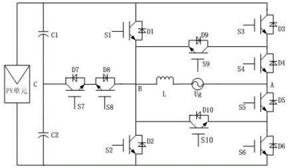
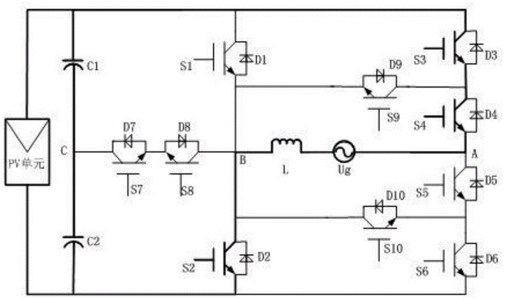
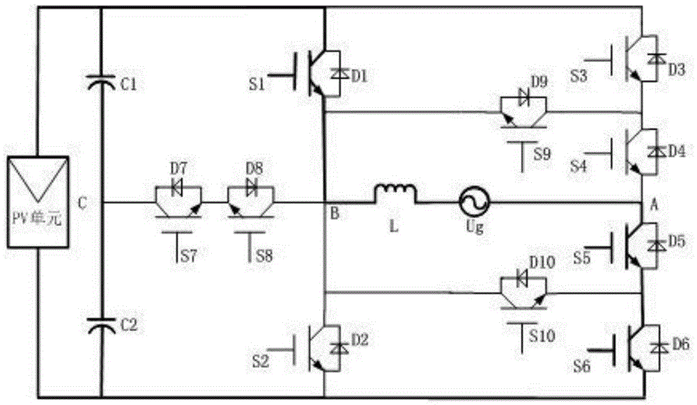
[0019] Working mode 1: Power switch tubes S2, S3, S4 are closed and the rest of the switch tubes are off, refer to figure 2 As shown, the A terminal of the inverter output is directly connected to the positive terminal of the PV side through the switch tubes S3 and S4, so the potential of the A terminal is the DC input voltage Ui; the B terminal of the inverter output is connected to the positive terminal of the PV side through the switch tube S2. The ground is connected, so the potential of the B terminal is zero, and the voltage U output by the inverter at this time AB is positive.

[0020] Working mode 2: Clamping switch tubes S7 and S8, power switch tube S4 and freewheeling switch tube S9 are closed and other switch tubes are turned off. If the power factor is equal to one, that is, the directions of voltage and current are the same, all are determined by A flows to B (transition from working mode 1 to working mode 2), and a freewheeling channel is formed through the dio...


PUM


Abstract

The invention relates to a switch tube clamping type transformerless photovoltaic inverter topology. The inverter topology in the scheme is optimized on the basis of the conventional H6 topology; the original single filter capacitor at the PV side is replaced by two filter capacitors C1 and C2 same in capacity and voltage; two clamping switch tubes S7 and S8 reversely connected in series are connected onto the inverter output B end and the intermediate C point of the two filter capacitors; a clamping unit is formed by adding the switch tubes in a circuit; with the help of a proper switch sequence, output voltage at A and B ends is clamped in the neutral point potential of a bus capacitor; therefore, the suspension problem when zero level is output is solved; in the zero level output stage, decoupling of a direct-current side and an inverter side is realized through a continuous-current circuit provided by a continuous-current switch tube; furthermore, the fact that the continuous-current loop also exists can be satisfied in the event that the power factor is less than 1; the parasitic oscillation of the loop is eliminated; the common-mode resonance phenomenon is inhibited; influence of the parasitic parameters of the power tubes is weakened; the switch tube clamping type transformerless photovoltaic inverter topology has the better leak current inhibiting capability; the switch tube clamping type transformerless photovoltaic inverter topology is simple in circuit structure and easy to realize; and the working efficiency of the system and the safety margin of a transformerless photovoltaic grid-connected inverter system are increased.

Description

technical field [0001] The invention relates to a switching tube clamp type transformerless photovoltaic inverter topology. Background technique [0002] With the increasing demand for energy, the development of new renewable energy has received widespread attention. The development of new energy and the improvement of energy utilization have become increasingly important. Among them, solar photovoltaic power generation has been rapidly developed in recent years because of its safety, pollution-free and abundant resources. development of. Due to the low photoelectric conversion efficiency and high price of solar photovoltaic panels, the promotion of photovoltaic power generation is limited to a certain extent. Therefore, how to reduce the cost of photovoltaic power generation system by improving the efficiency of power equipment has become a popular direction of photovoltaic power generation. [0003] In order to ensure the safety of users, the VDE standard has strict rest...

Claims


Application Information

Patent Timeline
IPC IPC(8): H02M7/5388H02M1/34
CPCH02M1/32H02M7/5388H02M1/0038Y02E10/56
Inventor 刘斌鞠嘉凌赵明
Owner NANCHANG HANGKONG UNIVERSITY
Learn More