
A Lensless Wide Beam Parallel Light Transmitting and Receiving System

A technology for transmitting, receiving, and transmitting systems, which is applied in the field of lensless wide-beam parallel light transmitting and receiving systems, can solve the problems of affecting the rotation or swing rate, inaccurate measurement results, and increased lens quality, so as to increase the rotation or swing rate, improve The effects of universality and widening the size range

Active Publication Date: 2019-03-22
TIANJIN ZHAORUI MEASURING TECH CO LTD
View PDF5 Cites 0 Cited by
  • Summary
  • Abstract
  • Description
  • Claims
  • Application Information

AI Technical Summary

Problems solved by technology

However, due to the larger size of the sample to be measured, the size of the required measurement system will increase accordingly, so the quality of the lens will increase accordingly
Because the optical measurement process may require the lens to rotate or swing, so its mass will increase the inertia, which will eventually affect the rotation or swing rate, making the measurement results inaccurate

Method used


Image

  • A Lensless Wide Beam Parallel Light Transmitting and Receiving System

Examples


Embodiment Construction

[0021] For a better understanding of the present invention, the present invention will be further described below with reference to specific embodiments and accompanying drawings.

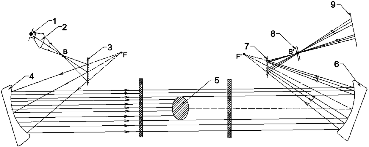
[0022] like figure 1 As shown in the figure, a wide-beam parallel light transmitting and receiving system without a lens includes a light transmitting system and a light receiving system. The transmitting plane mirror 3 at the lower right of the cylindrical prism 2 and the transmitting parabolic concave mirror 4 located obliquely below the left side of the transmitting plane mirror 3, the light receiving system includes a symmetrical arrangement with the transmitting parabolic concave mirror 4 in the horizontal direction. The receiving parabolic concave mirror 6, the receiving plane mirror 7 located obliquely to the left of the receiving parabolic concave mirror 6, and the CCD (Charge Coupled Device) array detector 9 located obliquely to the left of the receiving plane mirror 7 for receiving the im...


PUM


Abstract

The invention provides a no-lens wide-beam parallel light transmitting and receiving system, and the system comprises a point light source, a column-shaped prism, a transmitting plane mirror, a transmitting parabolic concave mirror, a receiving parabolic concave mirror, a receiving plane mirror, a filter, and a CCD array detector. The light emitted by the point light source is converted into a fan-shaped light band through the column-shaped prism. The fan-shaped light band is reflected by the transmitting plane mirror to the surface of the transmitting parabolic concave mirror, and then the transmitting parabolic concave mirror emits parallel light bands to the surface of a to-be-detected sample. Parallel light bands which are not sheltered by the to-be-detected sample come to the surface of the receiving parabolic concave mirror, and then the receiving parabolic concave mirror emits fan-shaped light bands to the receiving plane mirror. The receiving plane mirror enables the fan-shaped light bands to come out to the CCD array detector which is used for detecting the size of a dark angle generated because the to-be-detected sample shelters the parallel light bands. The beneficial effects of the invention are that the rotating or swinging speed in a detection process is increased because the weight of the system is small and no-lens design is employed, and the accuracy of a measurement result cannot be affected because of overlarge weight of a lens.

Description

technical field [0001] The invention relates to the technical field of electronic information measurement, in particular to a wide-beam parallel light transmitting and receiving system without a lens. Background technique [0002] Steel rolling is a pressure processing process in which the shape of steel ingots and billets is changed between rotating rolls. Through the rolling process, the rolling stock can obtain the desired shape. In order to detect whether the rolling stock reaches the target size during the rolling process, it is necessary to measure the rolling stock. The traditional measurement method is to use a lens for optical measurement. However, due to the larger size of the sample to be measured, the size of the required measurement system increases, and the mass of the lens increases accordingly. Since the lens needs to be rotated or oscillated during the optical measurement, excessive mass will lead to an increase in inertia, which will eventually affect th...

Claims


Application Information

Patent Timeline
Patent Type & Authority Patents(China)
IPC IPC(8): G01B11/00
CPCG01B11/00
Inventor 谭成章邢中柱
Owner TIANJIN ZHAORUI MEASURING TECH CO LTD
Learn More