
Uplift pile with unfolding barb and construction method thereof

A pipe pile and jacking technology, which is applied in sheet pile walls, foundation structure engineering, construction, etc., can solve problems such as obstacles to low-carbon and harmonious society construction, failure of pile sinking to meet design requirements, a large amount of manpower and material costs, etc. Achieve the effects of reducing the workload of workers on site, shortening the construction period, and controlling labor costs

Inactive Publication Date: 2016-05-04
陈明
View PDF6 Cites 6 Cited by
  • Summary
  • Abstract
  • Description
  • Claims
  • Application Information

AI Technical Summary

Problems solved by technology

In order to meet the bearing capacity requirements, it is usually economically unreasonable to increase the number of piles or increase the length of the pile itself.
In addition, due to the excessive length of the pile during the pile sinking process, it is easy to cause the pile body to break, the pile body is inclined, and the pile sinking cannot meet the design requirements; moreover, due to the limitation of transportation, the long piles are usually segmented during prefabrication. Prefabricated, after being transported to the site in sections, the pile body needs to be lengthened during the pile sinking process, resulting in a lot of manpower and material costs; moreover, the pile body is lengthened on site, and the quality is affected by site conditions, weather and human factors. , There are often loose and cracked piles; traditional extensive construction methods have seriously hindered the construction of a low-carbon and harmonious society

Method used


Image

  • Uplift pile with unfolding barb and construction method thereof
  • Uplift pile with unfolding barb and construction method thereof
  • Uplift pile with unfolding barb and construction method thereof

Examples


Embodiment Construction

[0036] In order to make the object, technical solution and advantages of the present invention clearer, various embodiments of the present invention will be described in detail below in conjunction with the accompanying drawings. However, those of ordinary skill in the art can understand that, in each implementation manner of the present invention, many technical details are provided for readers to better understand the present application. However, even without these technical details and various changes and modifications based on the following implementation modes, the technical solution claimed in each claim of the present application can be realized.

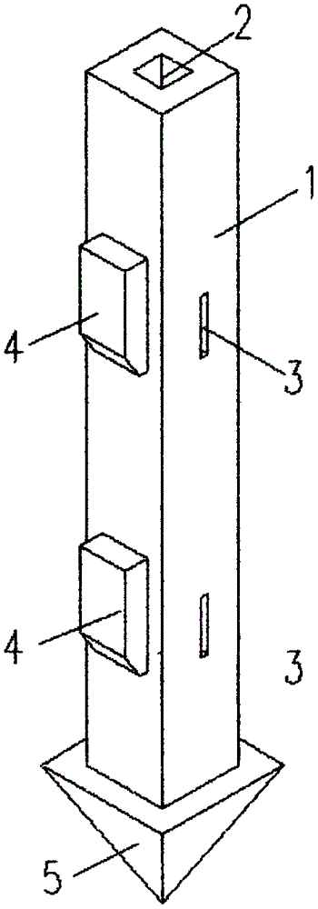
[0037] Such as figure 1 As shown, a pullout-resistant tubular pile with expanded barbs includes prefabricated tubular piles that are hammered or statically pressed into the soil layer. The prefabricated tubular piles include but are not limited to square pipes as shown in the figure, and can also be such as Round tube, poly...


PUM


Abstract

The invention discloses an uplift pile with an unfolding barb and a construction method thereof. The uplift pile comprises a precast tubular pile. The precast tubular pile comprises a maternal pile and a pile tip, wherein a pile body of the maternal pile extends from a pile tail to a cavity of the pile tip, one or more layers of vane pushing-away holes communicating with the cavity are formed in the pile wall of the maternal pile in the length direction of the pile body, the lower edges of the side, far away from the cavity, of the vane pushing-away holes are provided with vanes through rotary devices, the vanes can rotate away from the cavity around the rotary devices, and the cavity is provided with a force application part used for pushing the vanes away from the vane pushing-away holes. The construction method with the uplift pile with the unfolding barb is shown in the specification. Compared with a traditional precast pile, the unfolding vanes attached to the pile body work together with a soil body, so that the anti-floating design capacity of the uplift pile is greatly improved, the bearing capacity of the pile is improved by several times or even dozens of times, the number of piles and the length of the pile are greatly reduced, and the comprehensive benefits are quite remarkable.

Description

technical field [0001] The invention relates to the fields of industrial and civil construction, in particular to an anti-pull pipe pile with unfolded barbs and a construction method thereof, which is used for foundation engineering in construction engineering. Background technique [0002] Since the 21st century, with the rapid development of my country's economic construction, the utilization of underground space has become a new development direction. It is also receiving more and more attention. But in my country's coastal areas, the groundwater level is generally higher. Underground buildings and structures in high water level soil layers often bear greater water buoyancy. In order to reduce the impact of water buoyancy on underground structures, uplift pile foundations are usually required. For traditional precast concrete square piles and tubular piles, the bearing capacity of the pile usually depends on the friction force of the side wall of the pile. Due to the ...

Claims


Application Information

Patent Timeline
IPC IPC(8): E02D5/48E02D5/24E02D5/30
CPCE02D5/48E02D5/24E02D5/30
Inventor 陈明
Owner 陈明
Learn More