Drill pipe dismounting device for pile driver

A technology for pile drivers and drill pipes, which is applied in the direction of drill pipes, drill pipes, sheet pile walls, etc. It can solve the problems of inconvenient disassembly and assembly of the connection between the drill pipe and the grouting mechanism, poor stability of the drill pipe, and low connection strength. Simple and reasonable structure, high connection strength and good stability

Active Publication Date: 2017-05-03
浙江兆弟技术有限公司
View PDF6 Cites 0 Cited by
  • Summary
  • Abstract
  • Description
  • Claims
  • Application Information

AI Technical Summary

Problems solved by technology

[0004] The above-mentioned solution solves the problem of poor stability of the drill pipe of the existing piling machine to a certain extent, but the solution still exists: the connection between the drill pipe and the grouting mechanism is not convenient to disassemble, the connection strength is low, and the problem of mutual detachment is easy to occur

Method used


Image

  • Drill pipe dismounting device for pile driver
  • Drill pipe dismounting device for pile driver
  • Drill pipe dismounting device for pile driver

Examples


Embodiment Construction

[0026] The present invention will be described in further detail below in conjunction with the accompanying drawings and specific embodiments.

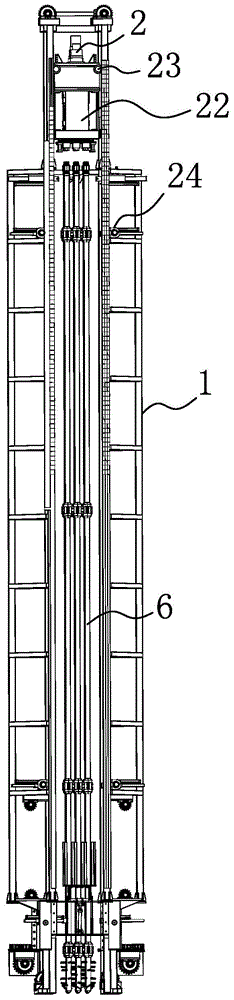
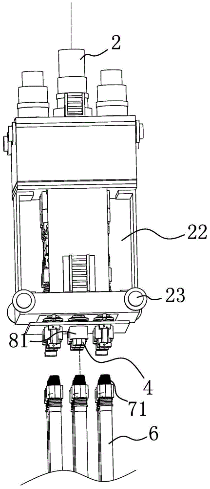
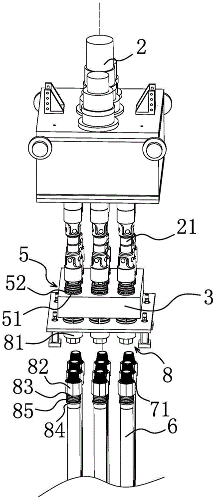
[0027] Such as Figure 1-4 As shown, the drill pipe dismounting device of this pile driver includes a frame 1, and a grouting plate 3 connected to the power head 2 is movable on the frame 1, wherein the power head 2 here passes through several universal joints 21 respectively. Corresponding to and connected to the grouting plate joints 4 one by one, the power head 2 and the grouting plate 3 are both arranged on a grouting connecting seat 22, and a number of grouting plate joints 4 are pierced on the grouting plate 3, and the grouting plate joints 4 are rotated in the circumferential direction respectively. The connecting structure 5 is connected with the grouting plate 3, and the circumferentially rotating connecting structure 5 here can include several mounting holes 51 arranged on the grouting plate 3, and the grouting plate joints ...


PUM


Abstract

The invention belongs to the technical field of construction equipment, and particularly relates to a drill stem dismounting and mounting device of a pile driver. By adopting the drill stem dismounting and mounting device, the problems that current drill stems of the pile driver are not convenient to dismount and mount and the like are solved. The drill stem dismounting and mounting device comprises a rack, wherein a grouting plate which is connected with a power head is movably arranged on the rack; a plurality of grouting plate connectors are arranged on the grouting plate in a penetration manner; the grouting plate connectors are separately connected with the grouting plate through a peripheral rotary connection structure; a plurality of drilling stem bodies which are in one-to-one correspondence with the grouting plate connectors are arranged below the grouting plate connectors; the drill stem bodies are connected with the grouting plate connectors through threaded connection structures; and peripheral positioning structures which can peripherally position the drill stem bodies and the grouting plate connectors are arranged between the drill stem bodies and the grouting plate connectors. The drill stem dismounting and mounting device has the advantages that the structure is simple and reasonable; the connection parts of the drill stems and a grouting mechanism are convenient to dismount and mount; the stability is good; the connection strength of the drill stems is high; the drill stems are not separated from the grouting plate easily during peripheral rotation; and peripheral positioning of the drill stems and the grouting plate connectors are realized through pressure plate drivers.

Description

technical field [0001] The invention belongs to the technical field of construction equipment, in particular to a drilling rod dismounting device for a pile driver. Background technique [0002] At present, there are two types of piling machines used on construction sites: one is the rotary piling machine. The structure of this piling machine is a drill pipe suspension frame pulled up by a hoist, and the drill pipe bit is driven by the power head to form a hole in the underground drilling machine. The other is the impact hammer pile driver. The structure of this pile driver is to use the hoist to pull up the impact hammer and drop it repeatedly, and then lift it to realize pile driving. Among them, the rotary pile driver mainly realizes the purpose of drilling the underground drill pipe through the circumferential rotation of the drill pipe during piling. However, due to the long length of the drill pipe during actual construction, it is inconvenient to install and disassemb...

Claims


Application Information

Patent Timeline
Patent Type & Authority Patents(China)
IPC IPC(8): E02D5/34E21B19/18
CPCE02D5/34E21B19/18
Inventor 周兆弟
Owner 浙江兆弟技术有限公司
Why Eureka
Try Eureka