
Power pooling and distribution device for space vehicle power system control equipment

A space vehicle and power supply system technology, which is applied in the direction of output power conversion devices, electrical equipment structural parts, and transformation equipment structural parts, etc., can solve the problems of difficult wire fixing, poor maintainability, and heavy device weight, etc., and achieve improvement. Effects of maintainability, weight reduction, and ease of assembly and disassembly

Active Publication Date: 2018-08-03
SHANGHAI INST OF SPACE POWER SOURCES
View PDF4 Cites 0 Cited by
  • Summary
  • Abstract
  • Description
  • Claims
  • Application Information

AI Technical Summary

Problems solved by technology

[0004] The purpose of the present invention is to provide a high-power collection and distribution structure for the control equipment of the space vehicle power supply system, which is arranged at the middle part of the control equipment near the structural rib of the heat dissipation bottom plate, and solves the problem of small size and weight of the power supply system control equipment. Under the condition of light conditions, the problems of poor maintainability, heavy device weight, difficulty in fixing wires and poor heat dissipation in the traditional power collection and distribution structure of large space power collection and distribution structure

Method used


Image

  • Power pooling and distribution device for space vehicle power system control equipment
  • Power pooling and distribution device for space vehicle power system control equipment
  • Power pooling and distribution device for space vehicle power system control equipment

Examples


Embodiment 1

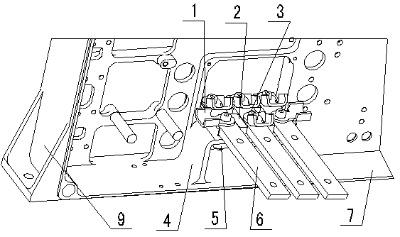
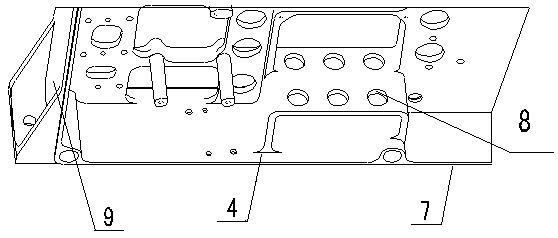
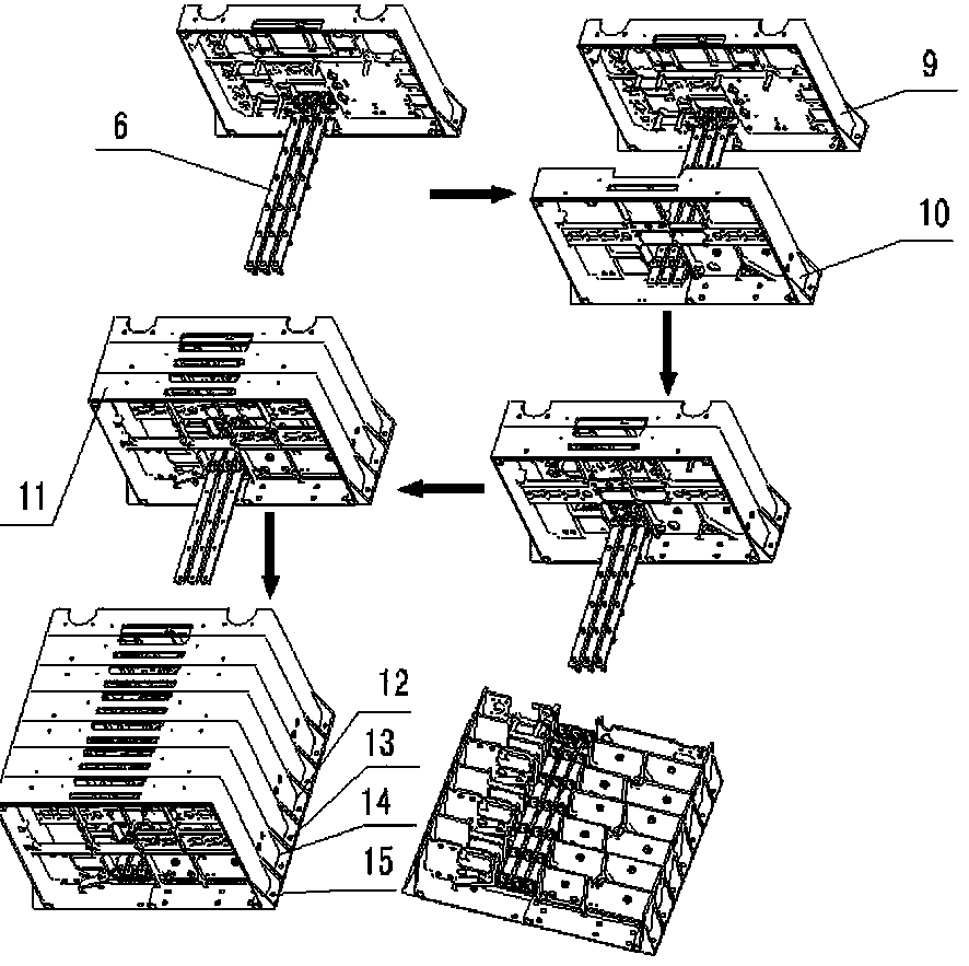
[0032] Such as image 3 As shown, the power collection and distribution device for the control equipment of the space vehicle power supply system provided by the present invention includes: the module A frame 9, the lower wall plate of the module A frame 9 is a heat dissipation bottom plate 7, and the heat dissipation bottom plate 7 is used to connect the supporting ribs of the bottom plate 4. The bottom plate reinforcement 4 is used to install the busbar 6; the upper insulating plate 2 located on the upper surface of the bottom plate reinforcement 4; the lower insulation plate 5 located on the lower surface of the bottom plate reinforcement 4; the busbar 6 runs through the lower insulation plate 5, The bottom plate reinforcing rib 4 and the upper insulating plate 2 are installed on the bottom plate reinforcing rib 4; it also includes: the busbar 1 located on the surface of the bus bar 6; the fastener 3 pressed on the surface of the bus bar 1.

[0033] The device also includes...


PUM


Abstract

The invention discloses a power concentration and distribution device for power supply system control equipment of a space craft. The device comprises a plurality of module frameworks, a heat dissipation bottom plate, a bottom plate reinforcing rib, an upper insulating plate, a lower insulating plate and copper bus bars; the bottom of each module framework is connected with the heat dissipation bottom plate and the module frameworks are vertical to the heat dissipation bottom plate; the bottom plate reinforcing rib is fixed on the heat dissipating bottom plate inside the module frameworks; the upper insulating plate is placed on the upper surface of the bottom plate reinforcing rib and the lower insulating plate is placed on the lower surface of the bottom plate reinforcing rib; the copper bus bars are mounted on the bottom plate reinforcing rib, penetrate through the lower insulating plate, the bottom plate reinforcing rib and the upper insulating plate and are fixed; the copper bus bars are vertical to the module frameworks. The power concentration and distribution device for power supply system control equipment of a space craft, provided by the invention, overcomes such problems of a traditional power concentration and electric energy distribution form under the limitation of small size and light weight as poor maintenanceability, heavy device weight, high difficulty in lead fixing and poor heat dissipation effect.

Description

technical field [0001] The invention relates to a large power collection and distribution structure used for control equipment of a space power supply system, in particular to a power collection and distribution device for a control equipment of a space vehicle power supply system. Background technique [0002] With the continuous development of space applications in our country, space power control equipment is developing in the direction of high-performance integration, long life, high reliability, miniaturization, maintainability and light weight. The power control equipment is becoming more and more complex, the number of internal components is increasing, and the integration density is increasing. Due to the limitation of equipment size and weight, collecting and distributing electric energy through cables can no longer meet the miniaturization, maintainability and lightness of control equipment. Quantitative requirements. [0003] In order to meet the requirements of ...

Claims


Application Information

Patent Timeline
Patent Type & Authority Patents(China)
IPC IPC(8): H02M7/00H05K7/20
CPCH02M7/003H05K7/209
Inventor 王德佳金磊叶帅宏黄忞屈诚志马季军俞静顾威
Owner SHANGHAI INST OF SPACE POWER SOURCES
Learn More