Large-visual-field array infrared detector

An infrared detector and a large field of view technology, which is applied in the direction of electric radiation detectors, instruments, measuring devices, etc., can solve the problems of reduced detection efficiency of detectors, increased device manufacturing costs, and limited device field of view to achieve superior performance , improve performance, improve the effect of device sensitivity

Inactive Publication Date: 2016-04-20
UNIV OF ELECTRONICS SCI & TECH OF CHINA
View PDF7 Cites 2 Cited by
  • Summary
  • Abstract
  • Description
  • Claims
  • Application Information

AI Technical Summary

Problems solved by technology

However, the sensitive elements of the sensitive layer in the infrared focal plane array are all located in a two-dimensional plane, while the current traditional line sensor is arranged in a one-dimensional linear arrangement, so that the detection directions of the sensitive elements on the array are all in the same direction, which makes The sensor is only sensitive to infrared light within a certain angle in front of it, but basically has no response to infrared light in other directions, which greatly limits the field of view of the device, making the effective visual range of the detector mainly concentrated in the front of the detector. The infrared light in the oblique direction of the detector is basically unable to respond, and the detection efficiency of the detector is greatly reduced.
At present, in order to improve the detection range of the detector, the common method is to increase the number of sensitive elements or use various optical lenses, which greatly increases the manufacturing cost of the device and the difficulty of the manufacturing process of the device while increasing the detection range.

Method used


Image

  • Large-visual-field array infrared detector
  • Large-visual-field array infrared detector
  • Large-visual-field array infrared detector

Examples


Embodiment Construction

[0028] The present invention will be described in further detail below in conjunction with the embodiments and accompanying drawings.

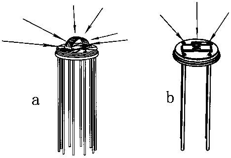
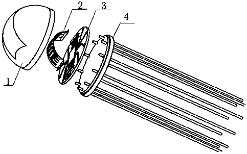
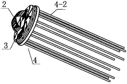
[0029] In this embodiment, a large field of view linear infrared detector is provided, and its structure is as follows: Figure 2-9 As shown, it includes a spherical package cap 1, a curved surface flexible sensitive circuit 2, a PCB board 3, and a package base 4; wherein, the spherical optical filter 1-1 is embedded on the spherical package cap shell 1-2 through a curved surface window to form a spherical package cap 1. The curved surface flexible sensitive circuit 2 includes a copper wire 2-1, a composite film sensitive layer 2-2, and a PET / PI flexible substrate 2-3. On the copper wire 2-1 on the PET / PI flexible substrate 2-3, they are electrically connected; the weak electrical signal generated by the composite film sensitive layer 2-2 is conducted to the PCB through the copper wire 2-1 The cable socket 3-2 on the board 3, the signal is co...


PUM


Abstract

The invention, which belongs to the technical field of the electronic material and elements, especially to a large-visual-field array infrared detector that is based on a flexible substrate and using a composite membrane as a sensitive unit, so that a defect of small field of view of the existing detector can be overcome. The provided detector comprises a packaging pedestal, a pin penetrating the pedestal, a PCB installed on the packaging pedestal, a sensitive circuit connected to the PCB, and a packaging cap. The detector is characterized in that the packaging cap is a spherical packaging cap; the spherical packaging cap is provided with a curve window; and a spherical filtering plate is embedded into the curve window. The sensitive circuit is a curve sensitive circuit and is in a curve shape corresponding to the curve window. With the detector, the large visual field of the array infrared detector is realized and the infrared visual field of the detector can be adjusted. Meanwhile, the provided detector has advantages excellent performance, simple structure, low production cost, and wide application range.

Description

technical field [0001] The invention belongs to the technical field of electronic materials and components, and relates to a large field of view array (line) infrared detector based on a flexible substrate and using a composite film as a sensitive unit. Background technique [0002] Infrared array detector is a common type of sensor, which has a wide range of uses; such as night vision, guidance, human body recognition, etc. There are three main types of array detectors suitable for integrated manufacturing: bolometers, pyroelectric detectors, and pyroelectric detectors; among them, bolometers and pyroelectric detectors are the focus of current researchers, and the The composite membrane array (line) based on composite materials has many advantages such as fast response speed, high detection rate, no need for refrigeration, excellent flexibility, and simple preparation process. In the infrared detection technology, the substrate, sensitive material, insulating structure, an...

Claims


Application Information

Patent Timeline
Patent Type & Authority Applications(China)
IPC IPC(8): G01J5/00G01J5/10
CPCG01J5/0025G01J5/10G01J2005/106
Inventor 罗文博吴勤勤吴传贵帅垚张万里
Owner UNIV OF ELECTRONICS SCI & TECH OF CHINA
Why Eureka
Try Eureka