
Permanent magnet high pressure nitrogen spring

A high-pressure nitrogen and permanent magnet technology, applied in the direction of magnetic springs, springs, springs/shock absorbers, etc., can solve the problem that system pressure alarms and system pressure compensation cannot be realized, ordinary mold nitrogen springs cannot meet the requirements, and cannot provide constant pressure Air source gas and other issues, to achieve the effect of promoting high-pressure gas control technology, simplifying mold design, and improving economic benefits

Inactive Publication Date: 2016-04-20
李长鸿
View PDF6 Cites 5 Cited by
  • Summary
  • Abstract
  • Description
  • Claims
  • Application Information

AI Technical Summary

Problems solved by technology

But so far there is no effective method for high and low pressure alarm and compensation for nitrogen gas spring system in the world
However, the research on the application of mold nitrogen springs in my country is in its infancy. Although some achievements have been made, there is still a big gap with foreign products in terms of performance. At the same time, the same problem exists: "the service life of mold nitrogen springs is When the mold closing height is small and the stroke is required to be long, ordinary mold nitrogen springs cannot meet the requirements” and “existing nitrogen spring inflators cannot provide constant pressure gas source gas” and other problems
For system pressure alarm and system pressure compensation can not be realized

Method used


Image

  • Permanent magnet high pressure nitrogen spring

Examples


Embodiment Construction

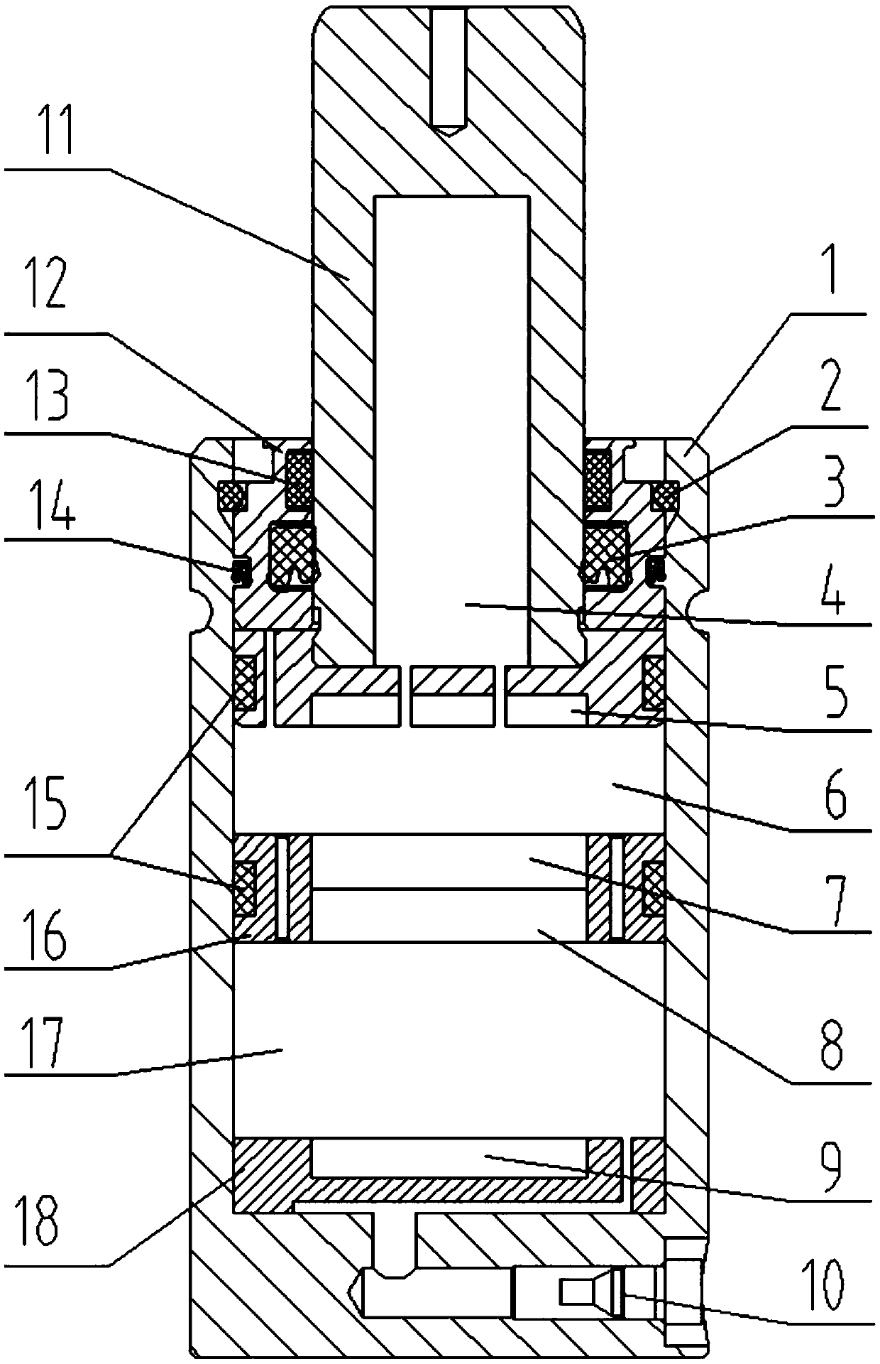
[0022] Such as figure 1 As shown, the permanent magnet high-pressure nitrogen gas spring includes cylinder body 1, permanent magnet A5, permanent magnet B7, permanent magnet C8, permanent magnet D9, charging valve 10, rod piston 11, upper end cover 12, rodless moving piston 16 and lower end Cover 18; the top of the cavity of the cylinder body 1 is equipped with an upper end cover 12 through the circlip 2, and is sealed by an O-ring 14; the rod piston 11 includes a piston rod and a piston body; a cavity A4 is opened in the piston rod, and the top of the piston rod There is a hoisting hole, the piston rod and the upper end cover 12 are slidably matched and sealed by the lip ring 3, and a dust-proof ring 13 is arranged between the piston rod and the upper end cover 12, and the dust-proof ring 13 is located above the lip ring 3; The body is slidingly fitted with the cavity of the cylinder body 1, a guide belt 15 is provided between the piston body and the cavity of the cylinder bo...


PUM


Abstract

The invention discloses a permanent magnet high pressure nitrogen spring which comprises a cylinder body, a permanent magnet A, a permanent magnet B, a permanent magnet C, a permanent magnet D, a gas charging valve, a rod piston, an upper end cover, a rodless movable piston and a lower end cover. A cavity A is formed in a piston rod. The permanent magnet A is installed at the bottom of a piston body. The piston body and the permanent magnet A are provided with a gas walking hole A. The permanent magnet B and the permanent magnet C are installed inside the rodless movable piston. The rodless movable piston is provided with a gas walking hole B. A cavity B is formed between the rodless movable piston and the piston body. The top of the lower end cover is provided with the permanent magnet D. The lower end cover is provided with a gas walking hole C. A cavity C is formed between the lower end cover and the rodless movable piston. The permanent magnet high pressure nitrogen spring overcomes defects in domestic and foreign technology and has the very important significance in improving safety, stability and buffering capacity of the nitrogen spring in industries such as mold manufacturing, saving energy, improving the product quality and reducing the product cost.

Description

technical field [0001] The invention relates to the technical field of elastic elements, in particular to a permanent magnet high-pressure nitrogen gas spring. Background technique [0002] In terms of the development of nitrogen gas springs, Germany and the United States are at the forefront of the world. The mold nitrogen gas spring developed by FIBRO Company of Germany and DADCO Company of the United States has been widely used in many industrial fields. But so far the world does not have an effective method for high and low pressure alarms and compensations for nitrogen gas spring systems. However, the research on the application of mold nitrogen springs in my country is in its infancy. Although some achievements have been made, there is still a big gap with foreign products in terms of performance. At the same time, the same problem exists: "the service life of mold nitrogen springs is When the mold closing height is small and the stroke is required to be long, ordinar...

Claims


Application Information

Patent Timeline
IPC IPC(8): F16F6/00
CPCF16F6/00
Inventor 李长鸿
Owner 李长鸿
Learn More