Multifunctional sludge pump room

A sludge pump house, multi-functional technology, applied in waterway systems, drainage structures, water supply devices, etc., can solve the problems of inconvenient operation and management, high project investment, large floor area, etc., to achieve simplified operation management mode, operation management Convenience and low engineering investment

Active Publication Date: 2016-04-20
SHANGHAI URBAN CONSTR DESIGN RES INST GRP CO LTD
View PDF5 Cites 1 Cited by
  • Summary
  • Abstract
  • Description
  • Claims
  • Application Information

AI Technical Summary

Problems solved by technology

The existing setting method not only occupies a large area and requires high engineering investment, but also is inconvenient for later operation and management.
[0003] In recent years, due to the improvement of environmental protection standards on the effluent indicators of sewage plants, and the land occupation control of sewage plants has become more and more stringent, it is difficult to meet the current land use control requirements and energy-saving needs by relying on the past sewage treatment methods
In particular, large and medium-sized sewage plants need multiple sets of lifting pump rooms and return sludge pump rooms, the distribution is relatively scattered, the operating cost and energy consumption are high, and the land occupation is large
[0004] In order to solve the above technical problems, many water treatment research institutions at home and abroad have conducted a lot of research work on sewage treatment methods. There are more and more equipment to be processed, and the floor area is getting larger and larger.
In many cities, land has become a bottleneck for the development of various facilities, and many equipment and technologies cannot be implemented due to the large area occupied

Method used


Image

  • Multifunctional sludge pump room
  • Multifunctional sludge pump room
  • Multifunctional sludge pump room

Examples


Embodiment Construction

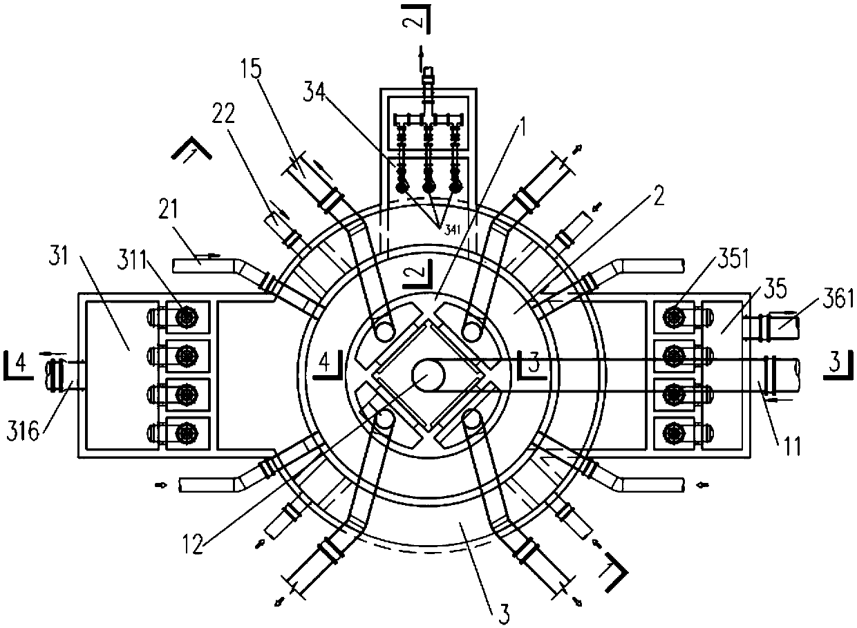
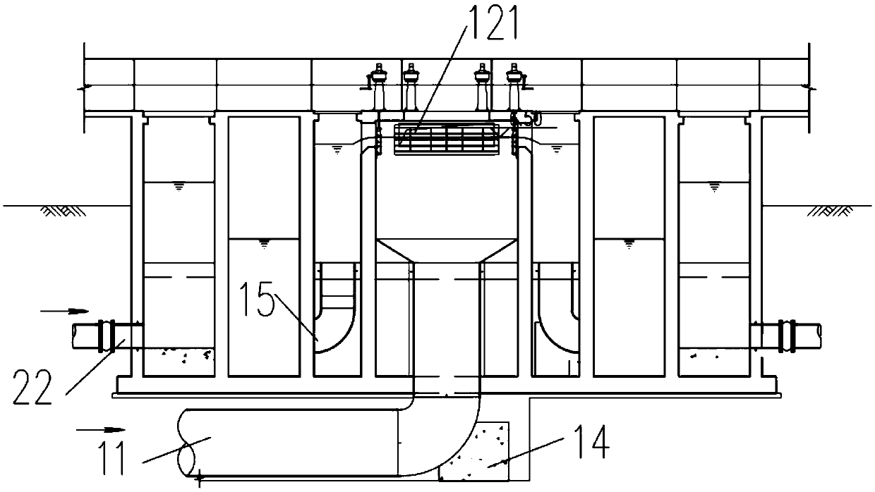
[0025] like Figure 1 to Figure 5 As shown, the present embodiment proposes a multifunctional sludge pump room, which includes an intermediate lifting pump room 31, a return sludge pump room 35, a surplus sludge pump room 34, and a water distribution well 12, wherein , the middle lifting pump room 31, the return sludge pump room 35, the remaining sludge pump room 34 and the water distribution well 12 are integrated and concentrated in a concentric circle manner.

[0026] Specifically, as figure 1 As shown, the concentric circles include three circles, which are the central circle 1, the middle circle 2 and the outer circle 3 from the inside to the outside. Among them, the middle lifting pump room 31 , the return sludge pump room 35 and the remaining sludge pump room 34 are respectively arranged in the outer ring 3 . Wherein, the middle ring 2 is connected with the return sludge pipe 21 of the secondary settling tank, and the outer ring 3 is connected with the outlet pipe 22 ...


PUM


Abstract

The invention discloses a multifunctional sludge pump room. The multifunctional sludge pump room at least comprises a middle promoting pump room, a return sludge pump room, an excess sludge pump room and a water distribution well. The middle promoting pump room, the return sludge pump room, the excess sludge pump room and the water distribution well are integrally and centrally arranged in a concentric-circle mode. The concentric circle comprises a central circle, a middle circle and an outer circle. The middle promoting pump room, the return sludge pump room and the excess sludge pump room are arranged on the outer circle. The outer circle is communicated with a secondary sedimentation tank water outlet pipe. A return sludge water collecting well and an excess sludge water collecting well are arranged on the middle circle and communicated with the corresponding pump rooms. The middle circle is communicated with a secondary sedimentation tank return sludge pipe. The water distribution well is arranged on the central circle. One end of the water distribution well is communicated with a biological tank through a water inlet pipe, and the other end of the water distribution well is communicated with a secondary sedimentation tank through a water distribution pipe. The multifunctional sludge pump room is in an integrated combined design, and is small in occupied space, low in project investment and operation cost and convenient to manage.

Description

technical field [0001] The invention relates to the technical field of sewage treatment, in particular to a multifunctional sludge pumping station. Background technique [0002] In the sewage treatment process of sewage treatment plants, it is often necessary to set up treatment facilities such as intermediate lifting pump room, return sludge pump room, excess sludge pump room, and water distribution well. However, at present, various functional facilities are usually set up independently. and are connected to each other by pipes. The existing setting method not only occupies a large area and requires high engineering investment, but also inconvenient operation and management in the later stage. [0003] In recent years, due to the improvement of environmental protection standards on the effluent indicators of sewage plants, and the land occupation control of sewage plants has become more and more stringent, it is difficult to meet the current land use control requirements ...

Claims


Application Information

Patent Timeline
IPC IPC(8): E03F5/22
CPCE03F5/22
Inventor 周传庭胡世琴胡龙陈轶高原唐建国
Owner SHANGHAI URBAN CONSTR DESIGN RES INST GRP CO LTD
Why Eureka
Try Eureka