
Arch rib face internal multi-point restrained and distributed tied-arch bridge

A multi-point constraint, tied arch bridge technology, applied in arch bridges, bridges, bridge maintenance and other directions, can solve the problems of increasing foundation construction costs, not easy to build old bridges, and using more materials.

Pending Publication Date: 2016-04-20
GUANGXI UNIV
View PDF2 Cites 9 Cited by
  • Summary
  • Abstract
  • Description
  • Claims
  • Application Information

AI Technical Summary

Problems solved by technology

At present, during the operation of arch bridges with concrete as the main material, under the action of temperature, vehicle load and other loads, transverse bridge cracks often appear in the mid-span of arch ribs, and a few have obvious downward deflection in the mid-span. Significantly decreased
[0003] In the prior art, such as the Chinese patent CN1483895A, a tie-bar arch bridge integrated with urban roads is designed. The tie-bar arch bridge is provided with stiffened longitudinal beams and beams, and the stiffened longitudinal beams are applied longitudinal prestress to overcome the constant and live loads. The horizontal thrust of the arch rib, this method uses more materials, increases the cost of foundation construction, and is not easy to construct the old bridge; Chinese patent CN101638883A designs an arch bridge, and the arch bridge is provided with multiple load-transferring bridges between the bridge deck and the arch ring The components that transmit the load extend radially from the arch ring to the bridge deck to reduce the mid-span bending moment. This method increases the bending moment of the bridge deck and reduces the driving comfort.

Method used


Image

  • Arch rib face internal multi-point restrained and distributed tied-arch bridge
  • Arch rib face internal multi-point restrained and distributed tied-arch bridge
  • Arch rib face internal multi-point restrained and distributed tied-arch bridge

Examples


Embodiment 1

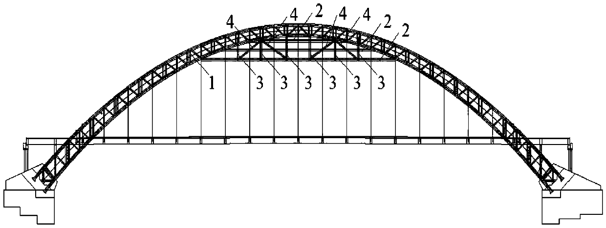
[0020] The arch bridge in Example 1 is an overhead arch bridge with a span of 100.00m, a reinforced concrete box-shaped arch rib, a net rise height of 11.10m, and a rise-span ratio of 1 / 9. The foundation, the abutment on both sides is the embedded abutment of mortar rubble, the enlarged foundation of open cut, and the longitudinal beam (2), the column (3) and the diagonal rod (4) are added under the arch rib (1), and the arch rib (1 ) bending stiffness and compressive stiffness are 7.23×10¹¹kN·m2 and 1.24×10⁸kN·m respectively; horizontal steel truss longitudinal beams (2) with lengths of 20m, 35m and 50m are erected respectively, and their bending stiffness and compressive stiffness are both They are 3.62×10¹¹kN m2 and 1.24×10⁸kN m2 respectively, and the longitudinal beam (2) and the arch rib are fixed; five vertical steel bars with a compressive stiffness of 3.10×10⁷kN m are installed under the arch rib (1). The truss column (3), the top of the column (3) is hinged to the arc...

Embodiment 2

[0022] The arch bridge in Example 2 is an under-supported arch bridge with a span of 100.00m reinforced concrete box-shaped arch ribs, a net rise height of 11.10m, and a rise-span ratio of 1 / 9. A longitudinal beam (2) is added below the arch rib (1) , columns (3) and diagonal rods (4), arch ribs (1) have bending stiffness and compressive stiffness of 7.23×10¹¹kN m2 and 1.24×10⁸kN m2 respectively; Steel truss longitudinal beam (2), its flexural rigidity and compressive rigidity are 5.10×10¹¹kN m2, 1.24×10⁸kN m2 respectively, longitudinal beam (2) and arch rib are all fixed; arch rib (1) below Set up 6 vertical steel truss columns (3) with a compressive stiffness of 4.95×10⁷kN·m, the top of the columns (3) is hinged to the arch rib (1), and the bottom is fixed to the 50m longitudinal beam (2). The joints are respectively 15m, 19m, 23m, 27m, 31m and 35m, and the column body (3) is fixedly connected with the other two longitudinal beams; a diagonal web bar (4) is set between two a...

Embodiment 3

[0024] The arch bridge in Example 3 is an overhead arch bridge with a span of 100.00m, a reinforced concrete box-shaped arch rib, a net rise height of 11.10m, and a rise-span ratio of 1 / 9. The foundation, the abutment on both sides is the embedded abutment of mortar rubble, the enlarged foundation of open cut, and the longitudinal beam (2), the column (3) and the diagonal rod (4) are added under the arch rib (1), and the arch rib (1 ) The bending stiffness and compressive stiffness are 7.23×10¹¹kN m2 and 1.24×10⁸kN m respectively; the erection length is 45m, and the bending stiffness and compressive stiffness are 7.23×10¹¹kN m2 and 1.24×10⁸kN m2 respectively The truss is used as the longitudinal beam (2), and the longitudinal beam (2) is fixedly connected to the arch rib; four vertical steel truss columns (3) with a compressive stiffness of 6.20×10⁷kN·m are arranged under the arch rib (1), The top of the column (3) is hinged to the arch rib (1), and the bottom end is fixed to ...


PUM


Abstract

The invention discloses an arch rib face internal multi-point restrained and distributed tied-arch bridge. A plurality of longitudinal beams connected with an arch rib are arranged below the arch rib, and thus a tie bar capable of resisting constant and live load action of the arch rib and balancing the horizontal thrust in a distributed mode is formed. Vertical stand columns and diagonal web members are arranged on the longitudinal beams and connected with the bottom face of the arch rib, an elastic restraint supporting system is formed in the surface of the arch rib, and thus the integral rigidity and strength of the arch rib are enhanced. Compared with a span arch bridge, the arch rib face internal multi-point restrained and distributed tied-arch bridge has smaller midspan arch rib bending moment and smaller arch springing horizontal thrust, has higher arch rib stability and higher stable bearing capability, and has smaller midspan deformation, and thus travel comfort is improved; in addition, the workload and cost for foundation construction are reduced.

Description

technical field [0001] The invention belongs to a tie-bar arch bridge, in particular to a multi-point constrained and distributed tie-bar arch bridge in the arch rib plane. Background technique [0002] Tied arch bridge is a combination of two basic structural forms of arch and beam, which jointly bear the load, give full play to the structural performance and combined effect of beam bending and arch compression, and the horizontal thrust of the arch end is supported by tie rods, so that the arch end support No horizontal thrust is produced. At present, during the operation of arch bridges with concrete as the main material, under the action of temperature, vehicle load and other loads, transverse bridge cracks often appear in the mid-span of arch ribs, and a few have obvious downward deflection in the mid-span. Significantly decreased. [0003] In the prior art, such as the Chinese patent CN1483895A, a tie-bar arch bridge integrated with urban roads is designed. The tie-b...

Claims


Application Information

Patent Timeline
Patent Type & Authority Applications(China)
IPC IPC(8): E01D4/00E01D22/00
CPCE01D4/00E01D22/00
Inventor 谢肖礼王波谭洪河郝天之向桂兵邓小康唐冬云
Owner GUANGXI UNIV
Learn More