
A bush pressing mechanism

A technology of pressing mechanism and bushing, applied in the field of pressing machine, can solve the problems of inaccurate pressing position of bushing, reduce production efficiency, low bearing pressure, etc., to improve product qualification rate, simple structure, and increase bearing pressure. Effect

Active Publication Date: 2020-05-12
BOZHON PRECISION IND TECH CO LTD
View PDF8 Cites 0 Cited by
  • Summary
  • Abstract
  • Description
  • Claims
  • Application Information

AI Technical Summary

Problems solved by technology

However, according to the applicant's reflection, although the cylinder joint can realize compensation for the coaxiality deviation between the cylinder and the used device during use, there are still some deficiencies: the circular boss of the upper joint of the cylinder joint is set In the wide groove of the lower joint, there is an arc-shaped contact between its circumference and the wide groove, so as to realize automatic compensation for the coaxiality deviation between the cylinder and the used device, and the end surface of the circular boss and the wide groove of the lower joint Due to the stress fit between the two, when the cylinder drives the cylinder joint down, there will still be a misalignment between the upper joint and the lower joint, resulting in a certain angle deviation when the lower joint is pressed down vertically, and there will be a The pressing position of the bushing is not accurate, the pressure is small, the scrap rate is high, and the production efficiency is reduced

Method used


Image

  • A bush pressing mechanism
  • A bush pressing mechanism
  • A bush pressing mechanism

Examples


Embodiment 1

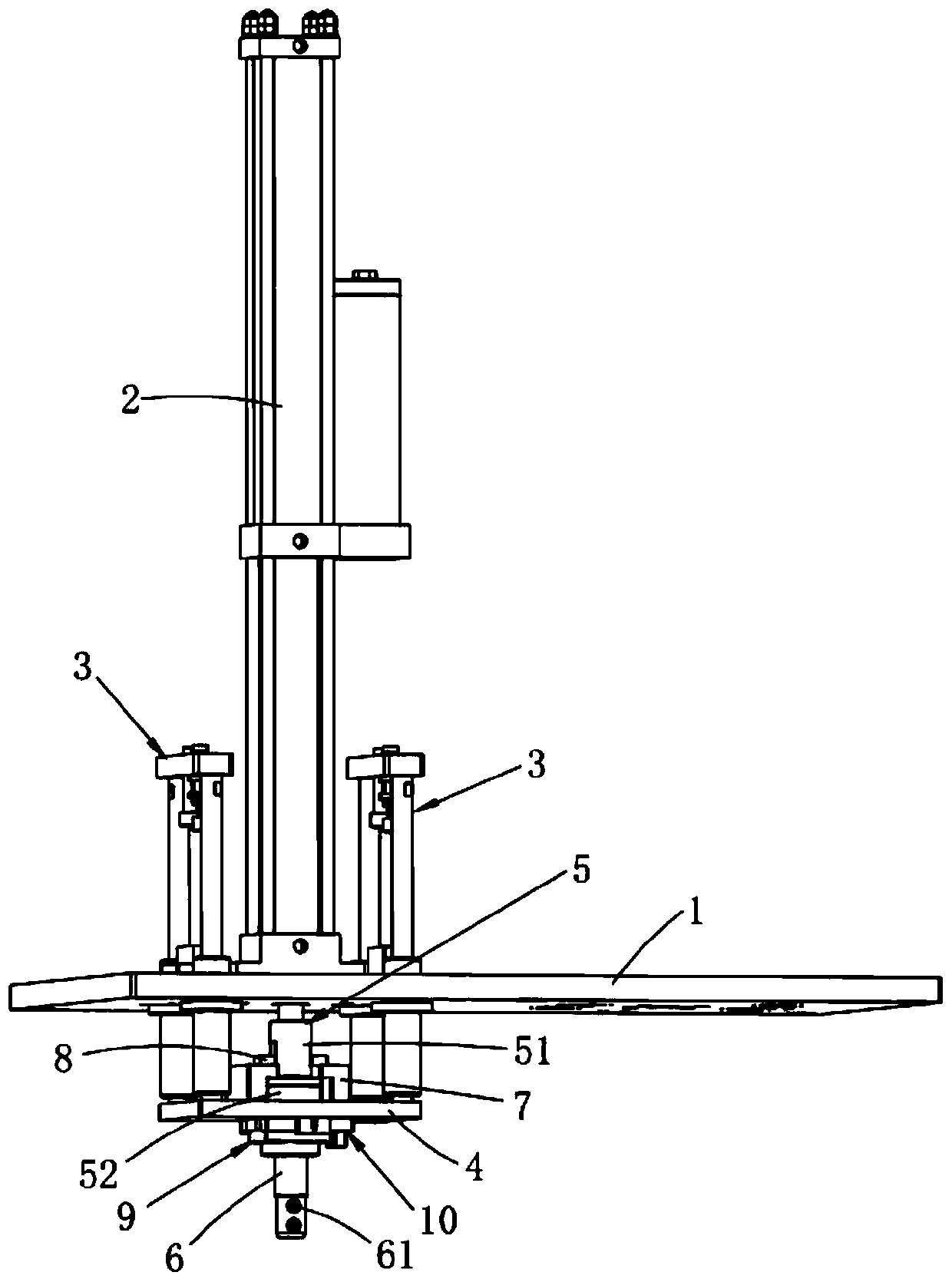
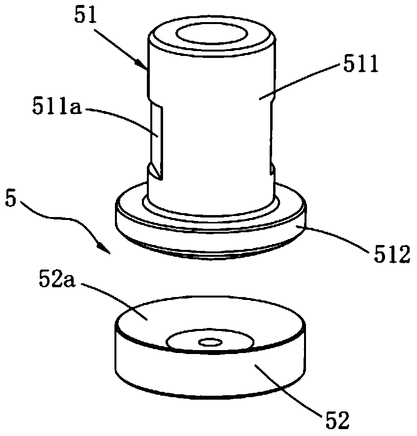
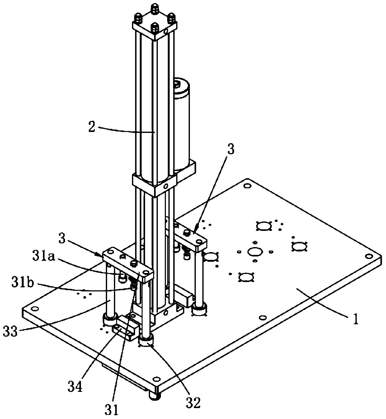
[0029] like figure 1 and figure 2 As shown, the present invention provides a bush pressing mechanism, including a base plate 1, a cylinder 2, a guide limit mechanism 3, a pressure head mounting plate 4, a cylinder joint 5 and a pressure head 6, and the cylinder 2 is installed on the base plate 1 The two sides of the cylinder 2 are oppositely provided with a guide limit mechanism 3, the end of the guide limit mechanism 3 is fixed with a pressure head mounting plate 4, and the pressure head mounting plate 4 is located below the bottom plate 1; the cylinder joint 5 includes an upper joint 51 and a lower joint 52, the upper joint 51 is installed on the piston rod of the cylinder 2, the lower joint 52 is arranged on the upper part of the pressure head mounting plate 4, and the upper joint 51 is provided with a cylindrical part 511 and a circular arc from top to bottom. Boss 512, the upper end surface of the lower joint 52 is processed with an arc groove 52a matching the arc boss ...


PUM


Abstract

The invention relates to a bush pressing mechanism, comprising a bottom plate, an air cylinder, guiding limiting mechanisms, a pressure head installation plate, an air cylinder joint and a pressure head, wherein the air cylinder is arranged on the bottom plate; the guiding limiting mechanisms are oppositely arranged at two sides of the air cylinder; the tail ends of the guiding limiting mechanism are fixedly provided with the pressure head installation plate; the air cylinder joint comprises an upper joint and a lower joint; the upper joint is arranged on a piston rod of the air cylinder; the lower joint is arranged at the upper part of a pressure head connection plate; the upper joint is sequentially provided with a cylinder part and an arc convex platform from top to bottom; an arc groove is formed in the upper end face of the lower joint; the pressure head is fixedly connected with the lower joint; the pressure head is provided with an electromagnet. The bush pressing mechanism has the advantages that a separation-designed air cylinder joint is utilized, and the deviation in front-rear direction, left-right direction and coaxial direction in the vertical downward pressing process is compensated through the arc surface matching manner between the upper joint and the lower joint, therefore an automatic piloting function is realized, the downward pressing position precision is guaranteed with combination of an X-axis adjusting mechanism and a Y-axis adjusting mechanism, and the pressure borne by the pressure head is improved.

Description

technical field [0001] The invention relates to the technical field of pressing machines, in particular to a bush pressing mechanism. Background technique [0002] The bushing is a ring sleeve that acts as a gasket. It is mainly used in the field of valves. It is generally mounted on the valve cover with equal pressure to protect the valve stem passing through the valve cover and has a good sealing effect. In the automatic bushing mechanism, the product reaches the designated position through the incoming material assembly line, the automatic feeding mechanism clamps the product through the clamping jaw cylinder, the rotating cylinder rotates, and the stepping motor performs a shifting action to shift the product to the product shifting positioning mechanism Above, the product displacement and positioning mechanism shifts the product to the positioning carrier through displacement and positioning, and then the bushing is discharged through the vibrating plate, and the pressi...

Claims


Application Information

Patent Timeline
Patent Type & Authority Patents(China)
IPC IPC(8): B23P19/027B25B27/24
CPCB23P19/027B25B27/24
Inventor 吕绍林陈小刚姜汉豪王洪录陈昊
Owner BOZHON PRECISION IND TECH CO LTD
Learn More