
Turbine rotor disk balance hole machining method and machining tool

A technology of steam turbine rotor and processing method, which is applied in the direction of manufacturing tools, metal processing equipment, boring/drilling, etc., and can solve the problem of high failure rate and low success rate of balance holes, failure to ensure that the roundness of balance holes meets the requirements, etc. problems, achieve effective processing results, low processing costs, and prevent drilling deviation and vibration

Active Publication Date: 2016-04-20
JIN TONG LING TECH GRP CO LTD
View PDF9 Cites 1 Cited by
  • Summary
  • Abstract
  • Description
  • Claims
  • Application Information

AI Technical Summary

Problems solved by technology

[0004] In order to overcome the problems existing in the prior art that the roundness of the balance hole cannot be guaranteed to meet the requirements, and that the machining of the balance hole has a high failure rate and a low success rate, the present invention provides a method for machining the balance hole of a steam turbine rotor disk and Processing tool

Method used


Image

  • Turbine rotor disk balance hole machining method and machining tool
  • Turbine rotor disk balance hole machining method and machining tool
  • Turbine rotor disk balance hole machining method and machining tool

Examples


Embodiment Construction

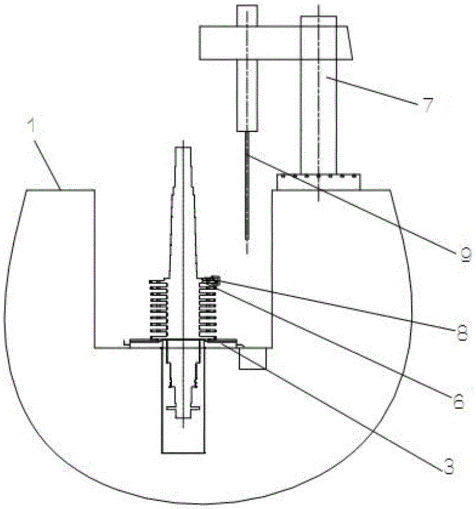
[0028] The present invention will be described in further detail below in conjunction with the accompanying drawings and embodiments. It should be understood that the specific embodiments described here are only used to explain the present invention, not to limit the present invention.

[0029] This embodiment discloses a method for machining the balance hole of the steam turbine rotor disc. The machining of such holes can be done in a horizontal or vertical way. If the horizontal machining is used, the machine tool used is a floor-type boring machine. , supported by a bracket, the rotor is placed horizontally on the machine table. For a relatively long rotor, the table of the floor boring machine is not long enough to effectively clamp the workpiece. In addition, the processing cost of CNC floor boring is relatively high. If vertical processing is adopted, the workpiece is processed vertically, and the radial drill is used for processing, and the processing cost is low. Usu...


PUM

PropertyMeasurementUnit
Lengthaaaaaaaaaa
Widthaaaaaaaaaa
Depthaaaaaaaaaa

Abstract

The invention provides a turbine rotor disk balance hole machining method and a machining tool. The machining method includes the following steps that, step 10, a workbench is arranged, wherein a pit is formed, the workbench is fixed to the bottom of the pit, a pressing plate is fixedly arranged on the workbench, a rotor workpiece is vertically placed on the workbench and pressed through the pressing plate, a through hole is formed in the center of the workbench, the lower portion of the workbench is aligned with the through hole to be provided with a steel pipe so that a round pit can be formed, and one end of each rotor stretches into the round pit; step 20, balance holes are machined, wherein a radial drill is installed on one side of the pit, a balance hole drill jig is installed in the to-be-machined balance hole of the first to-be-machined rotor, the radial drill is used to control a drill bit to start machining of the balance holes of the rotors according to guiding of the balance hole drill jig till machining of the balance holes of the to-be-machined rotors covered in the stroke of the drill bit is completed. According to the turbine rotor disk balance hole machining method, a vertical machining method is adopted, the workpiece is vertically machined, the radial drill is selected for machining, and machining cost is low.

Description

technical field [0001] The invention relates to the technical field of steam turbine rotor impeller processing, in particular to a method for machining a balance hole of a steam turbine rotor disc, and also provides a processing tool used in the method for machining a balance hole of a steam turbine rotor disc. Background technique [0002] The steam turbine rotor is the core component of the steam turbine and requires high machining accuracy. In steam turbine rotor processing technology, in order to balance the thrust of the end face of the impeller, there are usually steam balance holes on the impeller. The conventional processing method of the steam balance hole is to process the steam balance hole on a boring machine; Lying on the machine table, for a relatively long rotor, the table of the floor boring machine is not long enough to effectively clamp the workpiece. And those with flanges on the end face of the rotor cannot be finished on the boring machine, so the turni...

Claims


Application Information

Patent Timeline
IPC IPC(8): B23B35/00B23B39/12B23B41/00B23D79/04
CPCB23B35/00B23B39/12B23B41/00B23D79/04
Inventor 彭浩鸿石小露
Owner JIN TONG LING TECH GRP CO LTD
Learn More