
A high-efficiency scr flue gas denitrification system applied to boiler burning inferior coal

A technology for boiler combustion and low-quality coal, applied in the field of flue gas denitration system of SCR process, can solve the problems of consumption, reduction of denitration efficiency, wear, etc., and achieve the effect of improving denitration reaction efficiency, improving reaction environment conditions, and improving service life

Active Publication Date: 2018-12-25
SICHUAN JUNHE ENVIRONMENTAL PROTECTION
View PDF4 Cites 0 Cited by
  • Summary
  • Abstract
  • Description
  • Claims
  • Application Information

AI Technical Summary

Problems solved by technology

Under such a design arrangement, the fly ash contained in the flue gas and the various alkali metal oxides carried by it all pass through the catalyst and the reactor, and the entire denitrification system works in the "unclean" high-dust flue gas , has a great impact on the denitrification efficiency and the catalyst
Especially with the long-term consumption of national energy resources, the use of coal gangue and other low-quality coal has become an important fuel decision. Effective removal will greatly affect and damage the catalyst of the key reaction part of SCR, thereby reducing the efficiency of flue gas denitrification and curbing the efficient application of SCR flue gas denitrification process
[0005] In the traditional SCR denitrification process, the aggregate ash hopper is mainly installed at the entrance of the rising flue to collect dust, but the actual effect is poor, and due to the selection of the design position, there is still a large amount of dust in the horizontal flue, and it cannot be cleaned during operation. At the same time, the ash collected by the ash hopper is taken away by the flue gas and enters the reactor because it is not discharged in time, which has a great impact on the denitrification efficiency and catalyst life.
The catalyst is placed in a fixed reactor, and the flue gas passes through the reactor and flows across the surface of the catalyst in parallel. The catalyst unit is usually arranged vertically, and the flue gas flows from top to bottom. In order to remove the dust accumulated on the surface of the catalyst, the traditional process is to A large number of steam soot blowers and sonic soot blowers are required in the country, but the steam soot blowers are expensive, and the investment cost of the matching steam system is relatively high. On the basis of consuming a lot of steam energy, the actual effect is not ideal, and the catalyst will die in about two years. May be blocked by fly ash and unable to operate, resulting in reduced denitrification efficiency
At the same time, when using a steam soot blower to blow soot, it will cause certain wear and tear on the structural surface of the catalyst, thereby destroying the active structure of the catalyst and bringing about a significant increase in operating costs
[0006] Another key factor affecting the denitrification efficiency of SCR flue gas is whether the reducing agent can combine with NO X Thorough mixing, if the mixing is sufficient, it can ensure that the reducing agent and the flue gas have sufficient contact and reaction time, if the mixing is not sufficient, it will directly lead to a decrease in the denitrification efficiency

Method used


Image

  • A high-efficiency scr flue gas denitrification system applied to boiler burning inferior coal
  • A high-efficiency scr flue gas denitrification system applied to boiler burning inferior coal
  • A high-efficiency scr flue gas denitrification system applied to boiler burning inferior coal

Examples


Embodiment Construction

[0024] The present invention will be further described in detail below in conjunction with specific examples, but the implementation of the present invention is not limited thereto.

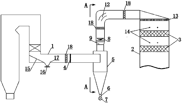
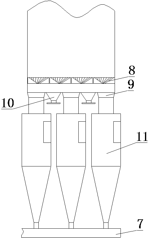
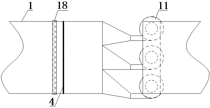
[0025] like figure 1 , figure 2 , image 3 As shown, a high-efficiency SCR flue gas denitrification system applied to boilers burning inferior coal types of the present invention includes an inlet flue 1 arranged behind the economizer and ammonia mixed with flue gas arranged behind the inlet flue 1 in sequence Unit, Reactor 2.

[0026] In the inlet flue 1, an anti-dusting device 15 is provided at the corner of the descending flue and the transverse flue, and a second ash unloading device 16 is provided below the anti-ashing device 15. Next to the second ash unloading device 16 A dust blocking device 17 is provided.

[0027] The ammonia and flue gas mixing unit includes an ammonia injection grid 4 for injecting reducing agent, a cyclone dust removal separation device 5 and a swirl plate devic...


PUM


Abstract

The invention relates to a flue gas denitration system and discloses an efficient SCR flue gas denitration system applied to a boiler for combusting low-grade coal. The system comprises an inlet flue (1), an ammonia and flue gas mixing unit and a reactor (2), wherein the inlet flue (1) is distributed behind an economizer, the ammonia and flue gas mixing unit and the reactor (2) are sequentially arranged behind the inlet flue (1), and a catalyst layer (3) is arranged in the reactor (2). The ammonia and flue gas mixing unit comprises an ammonia spraying grating (4) used for spraying a reduction agent, and a cyclone dust removal separation device (5). The cyclone dust removal separation device (5) is provided with an ash outlet (6), and an ash conveying device (7) is arranged at the ash outlet (6). According to the efficient SCR flue gas denitration system, the cyclone dust removal separation technology is adopted, a lot of dust carried in flue gas can be removed, the flue gas condition is improved before flue gas enters the catalyst layer, ammonia and the flue gas can be fully mixed, and the effect of a catalytic reduction reaction is enhanced.

Description

technical field [0001] The invention relates to a flue gas denitrification system, in particular to a flue gas denitrification system of an SCR process. Background technique [0002] Since the beginning of the 21st century, my country's environmental situation has become increasingly severe, and major pollutants such as smoke, sulfur dioxide, and nitrogen oxides have caused great harm to the atmospheric environment. Acid rain alone accounts for more than 29% of the country's land area. As the country pays more and more attention to the environment, the environmental protection standards for coal-fired boiler emissions are becoming increasingly stringent. In September 2014, the National Development and Reform Commission, the Ministry of Environmental Protection and the Energy Bureau jointly issued the "Coal Power Energy Conservation and Emission Reduction Upgrading and Transformation Action Plan (2014-2020)", requiring that by 2020 after the transformation of active coal-fir...

Claims


Application Information

Patent Timeline
Patent Type & Authority Patents(China)
IPC IPC(8): B01D53/90B01D53/56B01D45/16B01D45/18
CPCB01D45/16B01D45/18B01D53/56B01D53/8631B01D53/90B01D2258/0283
Inventor 杨波古志中罗启贵杨贤友聂海波蒲龙映张宇斌邓俊敬玲梅邓攀余珂莹
Owner SICHUAN JUNHE ENVIRONMENTAL PROTECTION
Learn More