Self-charging wireless mouse

A wireless mouse, self-charging technology, applied in the mouse field, can solve the problems of wireless mouse battery life limitation, wireless mouse unusable, replacement operation trouble, etc.

Inactive Publication Date: 2016-04-13
CHONGQING UNIV OF POSTS & TELECOMM
View PDF6 Cites 1 Cited by
  • Summary
  • Abstract
  • Description
  • Claims
  • Application Information

AI Technical Summary

Problems solved by technology

[0002] In the prior art, there are generally two ways to supply energy for the wireless mouse: first, a rechargeable battery and a charging interface are set in the wireless mouse, and when charging, the rechargeable battery is supplemented with electric energy through the charging interface; The mouse is powered; the second, a battery slot is set in the wireless mouse, and the mouse is powered by placing an ordinary battery in the battery slot; the problem that exists is: for the first energy supply method, when the electric energy in the rechargeable battery is exhausted Just need to carry out the charging operation, during the charging process, the wireless mouse cannot be used, which makes the endurance of the wireless mouse limited by the capacity of the rechargeable battery, and the charging operation is very troublesome; for the second energy supply method, the endurance of the wireless mouse will also be reduced. Due to the limitation of battery capacity, when the battery is exhausted, the battery needs to be replaced. The replacement operation is very troublesome, and this kind of battery usually uses chemical dry battery. The replaced battery is not only difficult to recycle, but also not conducive to environmental protection.

Method used


Image

  • Self-charging wireless mouse
  • Self-charging wireless mouse
  • Self-charging wireless mouse

Examples


Embodiment Construction

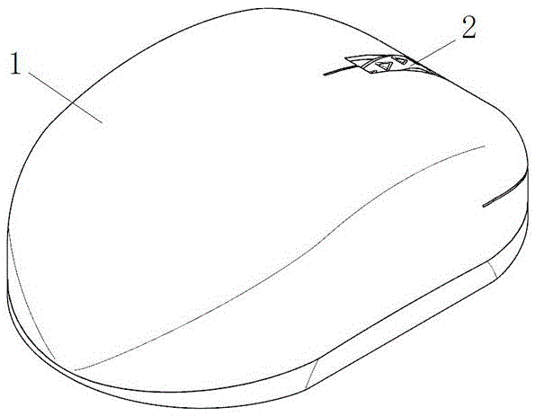
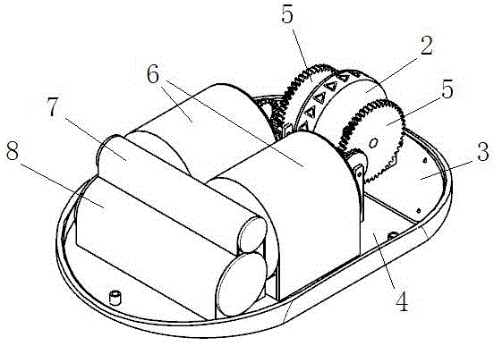
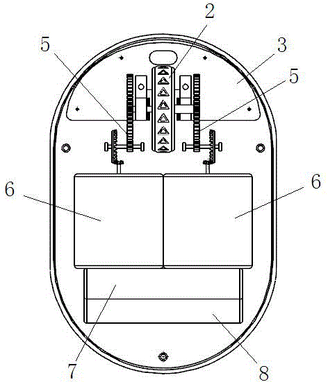
[0017] A self-charging wireless mouse, comprising a housing 1, a mouse wheel 2 and a mouse circuit board 3, its innovation lies in: a charging device is arranged in the housing 1; the charging device consists of a charging circuit board 4, a transmission mechanism 5, The small permanent magnet generator 6 and the rechargeable battery 7 are composed; the power input part of the transmission mechanism 5 is connected with the mouse wheel 2, and the power output part of the transmission mechanism 5 is connected with the rotor transmission of the small permanent magnet generator 6, and the small permanent magnet The electrical output part of the generator 6 is electrically connected to the charging circuit board 4 , the charging circuit board 4 is electrically connected to the rechargeable battery 7 , and the rechargeable battery 7 is electrically connected to the mouse circuit board 3 .

[0018] Further, the transmission mechanism 5 is composed of a cylindrical gear 5-1, a first tr...


PUM


Abstract

The invention discloses a self-charging wireless mouse. The self-charging wireless mouse comprises a casing, a mouse wheel and a mouse circuit board and is characterized in that a charging device is arranged in the casing and comprises a charging circuit board, a transmission mechanism, a small permanent magnet generator and a charging battery; the power input part of the transmission mechanism is in transmission connection with the mouse wheel, and the power output part of the transmission mechanism is in transmission connection with a rotor of the small permanent magnet generator; the electricity output part of the small permanent magnet generator is electrically connected with the charging circuit board, the charging circuit board is electrically connected with the charging battery, and the charging battery is electrically connected with the mouse circuit board. The self-charging wireless mouse has the benefits as follows: the self-charging wireless mouse can supply energy by collecting the kinetic energy of a human body and external power supply is not required.

Description

technical field [0001] The invention relates to a mouse, in particular to a self-charging wireless mouse. Background technique [0002] In the prior art, there are generally two ways to supply energy for the wireless mouse: first, a rechargeable battery and a charging interface are set in the wireless mouse, and when charging, the rechargeable battery is supplemented with electric energy through the charging interface; The mouse is powered; the second, a battery slot is set in the wireless mouse, and the mouse is powered by placing an ordinary battery in the battery slot; the problem that exists is: for the first energy supply method, when the electric energy in the rechargeable battery is exhausted Just need to carry out the charging operation, during the charging process, the wireless mouse cannot be used, which makes the endurance of the wireless mouse limited by the capacity of the rechargeable battery, and the charging operation is very troublesome; for the second energ...

Claims


Application Information

Patent Timeline
Patent Type & Authority Applications(China)
IPC IPC(8): G06F3/0354H02J7/32
CPCG06F3/03541H02J7/32Y02B40/00
Inventor 禄盛付豪萧红刘冰冰李庆华赵晓峰赵卫峰
Owner CHONGQING UNIV OF POSTS & TELECOMM
Why Eureka
Try Eureka