
a brake disc

A technology of brake disc and disc body, applied in the direction of brake disc, etc., can solve the problems of low strength of the outer peripheral part of the brake disc body 1, unable to stop the radial growth of cracks, affecting the service life of the brake disc, etc. Better performance, better heat dissipation, longer residence time

Active Publication Date: 2018-09-04
SHANDONG HAOXIN MACHINERY
View PDF6 Cites 0 Cited by
  • Summary
  • Abstract
  • Description
  • Claims
  • Application Information

AI Technical Summary

Problems solved by technology

With the above-mentioned structure, heat dissipation is carried out by reducing the wall thickness. Although it can improve the heat dissipation effect, the heat dissipation still cannot meet the needs of actual work.
[0006] Moreover, when braking, the brake caliper will clamp the outer peripheral portion of the brake disc body 1, and this part needs to bear a strong braking moment. However, on the outer peripheral portion of the brake disc body 1, two adjacent radial ribs 11 are relatively far away, so the outer peripheral strength of the brake disc body 1 is low, which will directly affect the service life of the brake disc
It is known from practice that as long as cracks appear on the disc body, most of them will extend and grow in the radial direction, and the radially extending structure of the radial ribs 11 cannot stop the radial growth of cracks, which will also affect the brake disc. service life

Method used


Image

  • a brake disc
  • a brake disc
  • a brake disc

Examples


Embodiment 1

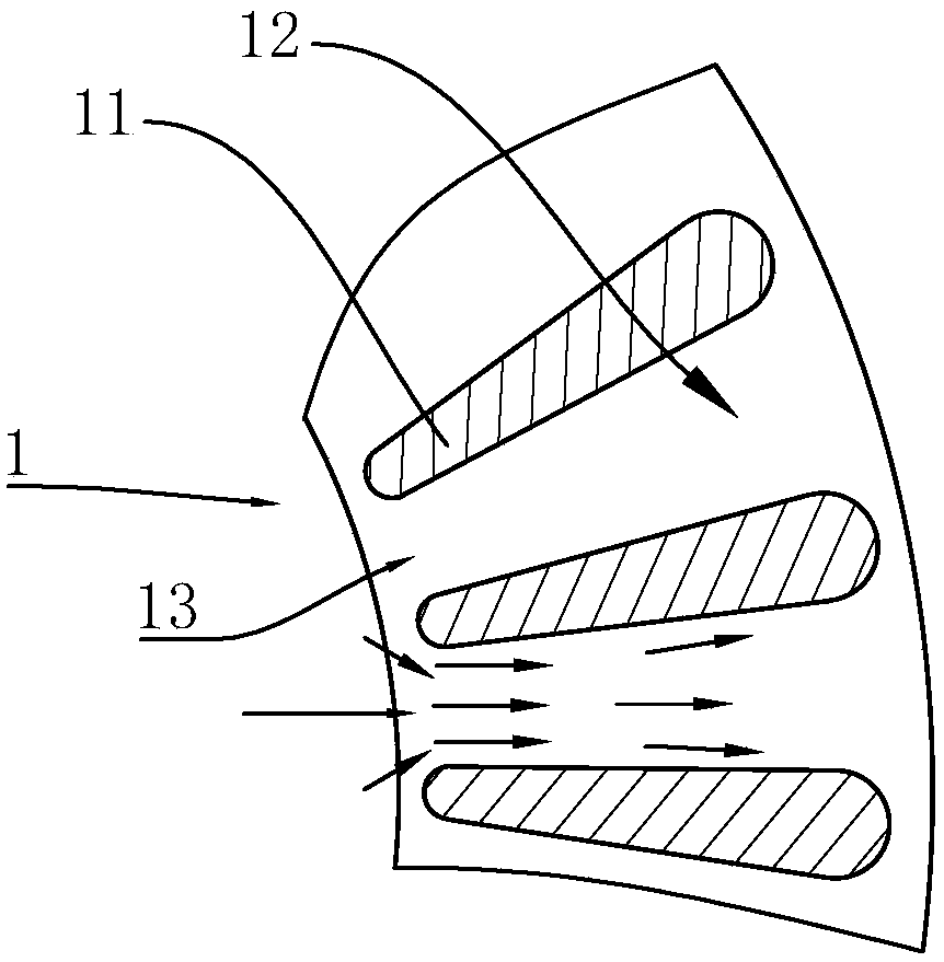
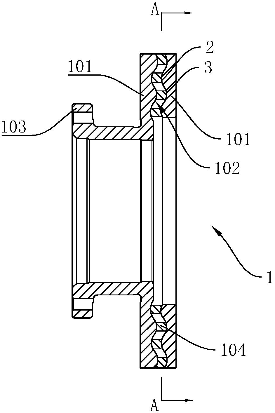
[0030] Such as figure 2 and image 3 Commonly shown, a brake disc includes a brake disc body 1, and the brake disc body 1 includes: two disc bodies 101 connected as one by connecting ribs 104, one of the disc bodies 101 is provided with a flange 103; the space between the two disks 101 constitutes the airflow channel 6, and each disk 101 has a disk surface 102 connected with the connecting rib 104, and the disk surface 102 of at least one disk 101 is wavy. The wave-shaped airflow passage 6 is formed between the two disk bodies 101 through the wave-shaped disk surface 102. When the airflow passes through the brake disc body 1, it will roll in the wave-shaped airflow passage 6 and form a certain acceleration. , not only increases the contact area between the airflow and the disc body 101, prolongs the residence time of the airflow in the airflow channel 6, but also increases the flow velocity of the airflow, so that the airflow is fully heated, that is to say: the airflow in t...

Embodiment 2

[0040] Such as figure 2 and Figure 4 Commonly shown, the specific structure of this embodiment is the same as that of Embodiment 1, the difference being:

[0041] The specific distributions of the annular ribs 4 and the radial ribs 5 on the disk surface 102 are different, specifically:

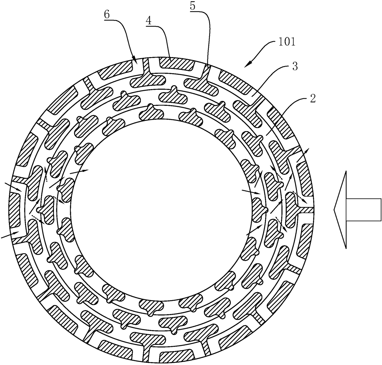
[0042] In the circumferential direction, there are multiple annular rib array groups and radial rib array groups. The annular ribs 4 are arranged in a staggered manner. Based on the outer circumference of the disk surface 102 , the radiating ribs 5 in the radiating rib array group extend from the outside to the inside, and extend to the corresponding annular ribs 4 . In this scheme, every three radial ribs 5 on the outer ring extend to the annular rib 4, and extend to the middle of the annular rib 4, and the radial ribs 5 on the inner ring are not connected to the annular rib 4; Air flow passages 6 are provided between the radial radial ribs 5 and the annular ribs 4 , between two adjacen...

Embodiment 3

[0046] Such as figure 2 and Figure 5 Commonly shown, the specific structure of this embodiment is the same as that of Embodiment 1, the difference being:

[0047] In a radially adjacent radial rib array group and an annular rib array group, the annular rib array group is located outside the radial rib array group, and the annular rib 4 in the annular rib array group is provided with a first point extending inward Head 401. Preferably, the radiating ribs 5 in the radiating rib array group are provided with second pointed portions 501 extending outward, and the second pointed portions 501 are arranged alternately with the first pointed portions 401 .

[0048] In this embodiment, the specific structure of the annular rib 4 and the radial rib 5 on the disk surface 102 is as follows:

[0049] A radial rib array group is provided near the outer and inner circumference of the disk surface 102, and an annular rib array group is arranged between the two radial rib array groups. Be...


PUM


Abstract

The invention discloses a brake disc. The brake disc comprises two disc bodies connected through a connecting rib, wherein space between the two disc bodies forms an air flow channel, each disc body is provided with a disc surface connected with the connecting rib, and the disc surface of at least one disc body is wave-shaped. The disc surface of at least one disc body is wave-shaped, so that the wave-shaped air flow channel is formed between the two disc bodies, air flow can tumble in the wave-shaped air flow channel when passing through the brake disc and certain acceleration can be formed, the contact area of the air flow with the disc bodies is increased, the retention time of the air flow in the channel is prolonged, the flow velocity of the air flow is increased, accordingly, the air flow is heated sufficiently, and the heat dissipation effect of the brake disc is improved. Meanwhile, the wave-shaped disc body facilitates resistance of radial growth of cracks, and the service life of the brake disc is prolonged effectively. When the disc surfaces of the two disc bodies are both wave-shaped and crests and troughs of the two disc surfaces are arranged correspondingly, the liquidity of the air flow is better.

Description

technical field [0001] The invention belongs to the technical field of automobile brake systems, and in particular relates to a brake disc. Background technique [0002] As we all know, the brake disc is fixed on the wheel hub of the vehicle, and it cooperates with the brake caliper to realize the braking of the vehicle. figure 1 A known brake disc is shown, the brake disc body 1 includes two discs, and the two discs are connected together by dozens of elongated radial ribs 11 in an annular array, radially, the The width of the radiating ribs 11 gradually narrows from the outside to the inside, and an airflow channel 12 is arranged between two adjacent radiating ribs 11. Along the radial direction, the width of the airflow channel 12 also gradually narrows from the outside to the inside, so that The narrower part forms a throttle zone 13 . [0003] When the vehicle brakes, the two discs rub against the brake calipers violently to generate a large amount of heat energy. Due...

Claims


Application Information

Patent Timeline
Patent Type & Authority Patents(China)
IPC IPC(8): F16D65/12
CPCF16D65/12
Inventor 吕继贤蒲光明
Owner SHANDONG HAOXIN MACHINERY
Learn More