
Automobile welding conveying line

A conveying line and welding technology, which is applied in the direction of conveyors, mechanical conveyors, auxiliary devices, etc., can solve the problems of reducing the accuracy of workpiece conveying, inability to achieve synchronization, complex and large structures, etc., and achieve improved conveying efficiency, easy maintenance, and conveying high efficiency effect

Active Publication Date: 2016-04-13
烟台达源自动化科技有限公司
View PDF6 Cites 7 Cited by
  • Summary
  • Abstract
  • Description
  • Claims
  • Application Information

AI Technical Summary

Problems solved by technology

[0002] At present, manual welding, manual handling, and manual transportation of workpieces in the automobile welding production line can no longer meet the requirements of the production cycle of the automobile welding assembly line. New welding and conveying equipment are emerging as the times require, and are constantly being updated and optimized, greatly improving The automation level of the automobile production line, however, the existing synchronous jacking and conveying equipment is realized by a jacking mechanism composed of multiple cylinders. Synchronous lifting, although this kind of automatic equipment reduces the labor intensity of workers and improves the conveying efficiency compared with manual conveying, but the structure is complex and huge, and the cost is high. The lifting of the cylinder is affected by the synchronous structure and often cannot realize the synchronization between each station. The damage of the equipment itself is large, which will reduce the accuracy of workpiece transportation for a long time, resulting in the appearance of unqualified products

Method used


Image

  • Automobile welding conveying line
  • Automobile welding conveying line
  • Automobile welding conveying line

Examples


Embodiment Construction

[0036]The principles and features of the present invention are described below in conjunction with examples, which are only used to explain the present invention and are not intended to limit the scope of the present invention.

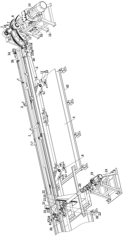
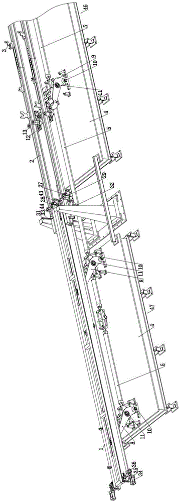
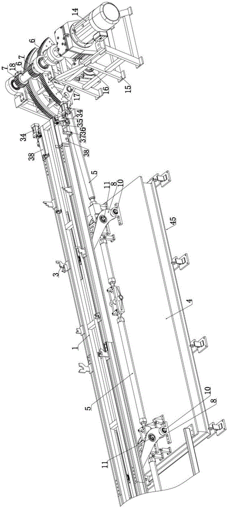
[0037] Such as Figure 1 to Figure 9 As shown, a kind of automobile welding conveying line, comprises the first station 45 that is arranged on the head end of the conveying line, a plurality of intermediate stations 46 and the empty station 47 that is arranged on the end of the conveying line, the first station and the empty station The stations are respectively provided with jacking frames 1, the jacking frames of the first station and the middle station are provided with two conveying beams in parallel, and the conveying beams are provided with supporting blocks 3 matched with workpieces, The jacking frame 1 and the conveying beam can move up and down synchronously under the action of the synchronous jacking mechanism, and the conveying beam can mov...


PUM


Abstract

The invention discloses an automobile welding conveying line, and belongs to the technical field of automobile white body manufacturing. The automobile welding conveying line comprises a first station arranged at the head end of the conveying line, a plurality of middle stations, and an empty station arranged at the tail end of the conveying line. The first station and the empty station are provided with jacking frames respectively. The jacking frame of the first station and the middle stations are provided with two conveying beams in parallel. The conveying beams are provided with supporting blocks matched with workpieces. The jacking frames and the conveying beams can synchronously ascend and descend through a synchronous jacking mechanism, and the conveying beams can move in the horizontal direction through a horizontal conveying mechanism. The automatic welding conveying line is simple in structure and easy to maintain. Meanwhile, automatic workpiece conveying can be achieved, workpiece positioning is accurate, the conveying efficiency is high, the workpiece conveying efficiency is greatly improved, and the multiple workpieces can be conveyed at the same time at a plurality of welding stations.

Description

technical field [0001] The invention relates to a conveying mechanism, in particular to an automobile welding conveying line, which belongs to the technical field of automobile manufacturing. Background technique [0002] At present, manual welding, manual handling, and manual transportation of workpieces in the automobile welding production line can no longer meet the requirements of the production cycle of the automobile welding assembly line. New welding and conveying equipment are emerging as the times require, and are constantly being updated and optimized, greatly improving The automation level of the automobile production line, however, the existing synchronous jacking and conveying equipment is realized by a jacking mechanism composed of multiple cylinders. Synchronous lifting, although this kind of automatic equipment reduces the labor intensity of workers and improves the conveying efficiency compared with manual conveying, but the structure is complex and huge, an...

Claims


Application Information

Patent Timeline
IPC IPC(8): B23K37/00B65G35/00
CPCB23K37/00B23K2101/006B65G35/00
Inventor 黄洪青孙顺徐兆康王成春
Owner 烟台达源自动化科技有限公司
Learn More