Eureka AIR delivers breakthrough ideas for toughest innovation challenges, trusted by R&D personnel around the world.

Wet electrostatic precipitator to prevent fouling of anode tubes

A wet electrostatic precipitator and anode tube technology, which is applied in the direction of external electrostatic separator, electrostatic separation, electrode cleaning, etc., can solve the problems of large thickness and area, affecting the electric field effect of anode tube and cathode tube, and reducing the dust removal efficiency of equipment

Active Publication Date: 2017-09-08
JIANGSU XINFUTE ENVIRONMENTAL PROTECTION TECH
View PDF9 Cites 0 Cited by
  • Summary
  • Abstract
  • Description
  • Claims
  • Application Information

AI Technical Summary

Problems solved by technology

However, when the wet electrostatic precipitator is running, there is an electric field between the anode tube and the cathode line, if a large amount of water passes through, it is easy to cause a short circuit and damage the equipment
Therefore, this method can only be carried out when the wet electrostatic precipitator is out of service
At the same time, due to the long-term accumulated scale thickness and area are often large, it is difficult to completely remove it by this method, and the residual scaling on the anode tube wall will affect the electric field effect between the anode tube and the cathode tube, causing equipment Decrease in dust removal efficiency

Method used


Image

  • Wet electrostatic precipitator to prevent fouling of anode tubes
  • Wet electrostatic precipitator to prevent fouling of anode tubes
  • Wet electrostatic precipitator to prevent fouling of anode tubes

Examples


Embodiment Construction

[0021] The present invention will be described in further detail below in conjunction with the accompanying drawings.

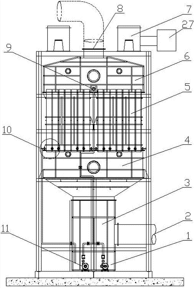
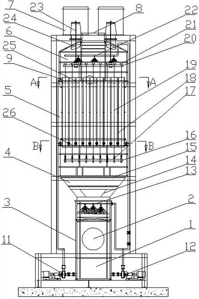
[0022] The wet electrostatic precipitator capable of preventing the fouling of the anode tube of the present invention includes a casing in which an inlet chamber 3, a gas distribution chamber 4, an anode chamber 5 and an outlet chamber 6 are sequentially arranged from bottom to top.

[0023] Such as figure 1 with figure 2 As shown, the side wall of the air inlet chamber 3 has an air inlet 2. There is a collecting tank 1 at the bottom of the air inlet chamber 3, and the collecting tank 1 is connected with a first circulating pump 12 and a second circulating pump 11. There is a second spray pipe 13 on the top of the intake chamber 3, and spray heads are evenly distributed on the lower side of the second spray pipe 13, and the second spray pipe 13 is connected to the first circulating pump 12 through a pipe.

[0024] Such as figure 1 with figure 2 As shown, the gas...


PUM


Abstract

The invention relates to a wet-type electric dust remover capable of preventing anode pipes from scaling. The wet-type electric dust remover comprises a shell. A gas inflow chamber, a gas distribution chamber, an anode chamber and a gas outflow chamber are sequentially arranged in the shell from bottom to top. The gas inflow chamber is provided with a gas inlet. A gas distribution board is arranged in the gas distribution chamber. The anode pipes are evenly distributed in the anode chamber. Cathode lines are suspended in the anode pipes respectively. A gas outlet is formed in the top of the gas outflow chamber. An insulation box is arranged on the shell. The wet-type electric dust remover is characterized in that a liquid collection box is arranged at the bottom of the gas inflow chamber and connected with a first circulating pump and a second circulating pump. A second spray pipe is arranged at the top of the gas inflow chamber and connected with the first circulating pump. An upper water carrying board and a lower water carrying board are arranged in the anode chamber and an overflow pipe is arranged on the upper water carrying board and connected with the second circulating pump. Water collection grooves are formed in the lower ends of the anode pipes and water outlets are formed in the pipe walls of the anode pipes. The shell is provided with water outflow pipes and the water outflow pipes are lower than the water outlets. By the adoption of the wet-type electric dust remover, crystals on the inner walls of the anode pipes can be removed in real time, scale is prevented from being generated, and it is guaranteed that the dust removing efficiency of equipment is not affected.

Description

Technical field [0001] The invention relates to a wet electrostatic precipitator, in particular to a wet electrostatic precipitator capable of preventing the fouling of anode tubes. It is mainly used for the collection and treatment of silicon oxide and acid-base waste liquid mist droplets in the production process of computer monitors and mobile phone panels. Treatment of harmful gas emissions in other chemical industries. Background technique [0002] With the development of the electronic information industry and the gradual expansion of application fields, the flat panel display industry has developed rapidly and has become an industry with a large market scale, rapid technology update, and a wide range of industries that promote significant benefits. At the same time, touch screen products have developed rapidly in recent years, and Oxide TFT, as the next generation of new semiconductor display technology, has unique advantages and is the main development direction for prepa...

Claims


Application Information

Patent Timeline
Patent Type & Authority Patents(China)
IPC IPC(8): B03C3/16B03C3/34B03C3/78
CPCB03C3/16B03C3/34B03C3/78
Inventor 朱永兵
Owner JIANGSU XINFUTE ENVIRONMENTAL PROTECTION TECH
Why Eureka
Eureka Blog
Learn More