
Very-low-profile cylindrical Luneberg lens antenna based on novel dielectric filling mode

A technology of Lunberg lens antenna and new medium, which is applied to antennas, electrical components, etc., can solve the problems of dense hole processing, large antenna loss, difficulty in processing and restricting use, etc., and achieve the effect of simple processing and low profile.

Active Publication Date: 2016-04-06
UNIV OF ELECTRONICS SCI & TECH OF CHINA
View PDF7 Cites 41 Cited by
  • Summary
  • Abstract
  • Description
  • Claims
  • Application Information

AI Technical Summary

Problems solved by technology

[0007] In the patent with the notification number CN102110893, an air-filled cylindrical lens antenna is disclosed. This antenna uses the propagation characteristic that the propagation constant of the TE wave in the planar waveguide is related to the height of the parallel plate. By controlling the height of the parallel plate to a certain Curve to achieve the required refractive index to achieve beamforming, but in order to transmit TE wave parallel plate waveguide thickness must be greater than λ / 2, this antenna is not suitable for use when the antenna is required to form an array along the axial direction, and for the millimeter wave high frequency band in The processing is only in the huge processing difficulty
In the patent with the notification number CN102110894, a partially dielectric-filled asymmetric cylindrical lens antenna is proposed. The antenna utilizes the correlation between the propagation constant of the TE wave in the slab waveguide and the dielectric constant of the medium there, and controls the parallel The plate is filled with a medium with a certain curve to achieve the required refractive index to achieve beamforming, but its processing difficulty in the high frequency band of millimeter waves seriously restricts its use
[0008] Southeast University Cui Tiejun et al. published a paper titled "Broadband planar Luneburglens based on complementary metamaterials" on AppliedPhysicsLetters.(vol.95, issue18, id.181901, 2009), using electromagnetic metamaterials to design a Luneburg lens antenna working in the Ku band, but due to The metal-attached PCB board is used to realize the metamaterial, resulting in excessive loss of the antenna and low aperture efficiency
OlivierLafond et al. designed a layered cylindrical lens antenna based on Lunberg lens theory in a paper entitled "AnActiveReconfigurableAntennaat60GHzBasedonPlateInhomogeneousLensandFeeders" published by IEEETRANSACTIONSONANTENNASANDPROPAGATION, VOL.61, NO.4, APRIL2013. The internal high dielectric constant layer of the lens antenna The technology equivalent to punching holes on the Teflon dielectric sheet with a higher dielectric constant is adopted, and the external low dielectric constant layer is realized by foaming technology. The reason why the external low dielectric constant The hole equivalent technology requires that the hole diameter of the hole should be less than one tenth of the wavelength. If the hole diameter is guaranteed to be less than one tenth of the wavelength in the V frequency band, the holes need to be processed too densely for the external low dielectric constant layer to be difficult to process. accomplish

Method used


Image

  • Very-low-profile cylindrical Luneberg lens antenna based on novel dielectric filling mode
  • Very-low-profile cylindrical Luneberg lens antenna based on novel dielectric filling mode
  • Very-low-profile cylindrical Luneberg lens antenna based on novel dielectric filling mode

Examples


Embodiment Construction

[0026] In order to make the purpose, technical solution and advantages of the present invention clearer, the present invention will be further described in detail below in conjunction with the implementation methods and accompanying drawings.

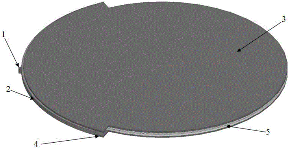
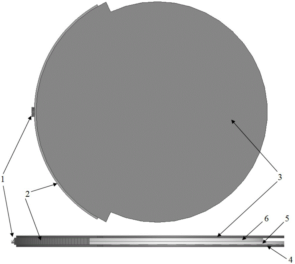
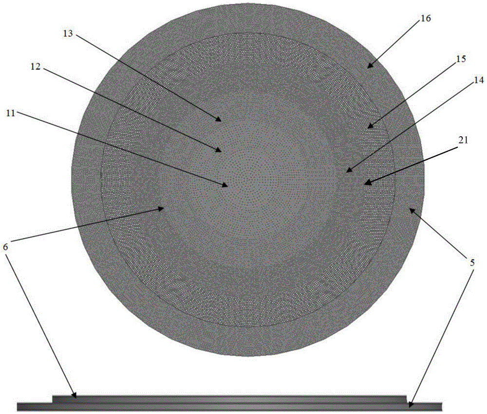
[0027] see figure 1 , figure 2 and image 3 , the cylindrical Lunberg lens antenna of the present invention comprises the cylindrical Lunberg lens between the upper metal cover plate 3 and the lower metal cover plate 4, and is fed by 3 open ridge waveguides (the spacing between adjacent feed sources is 1.5°) , to realize antenna multi-beam overlap within 3dB beam width) arc feed array 1 formed by arranging along the circumference where the focal point of the cylindrical Lunberg lens is located, and the arc-shaped feed array 1 located on the non-radiative aperture of the cylindrical Lunberg lens Metal reflective baffle 2 (which can effectively reduce the front-to-back ratio of the antenna radiation pattern), circular upper filling die...


PUM


Abstract

The invention discloses a very-low-profile cylindrical Luneberg lens antenna based on a novel dielectric filling mode. The very-low-profile cylindrical Luneberg lens antenna comprises a cylindrical Luneberg lens, an arc feed source array (1) and an arc metallic reflection baffle plate (2), wherein the cylindrical Luneberg lens is arranged between an upper metal cover plate (3) and a lower metal cover plate (4), the arc feed source array (1) is arranged on a focal line of the cylindrical Luneberg lens, the arc metallic reflection baffle plate (2) is arranged on a non-radiation aperture of the cylindrical Luneberg lens, the cylindrical Luneberg lens comprises an upper filling dielectric piece (6) and a lower filling dielectric piece (5) which have different radii, n layers of through holes (21) and m layers of through holes (21) which have different distribution densities are respectively arranged on the upper filling dielectric piece (6) and the lower filling dielectric piece (5) from circle centers towards theoutside, m is larger than n, and the effective dielectric constants of the front n layers of two dielectric pieces are correspondingly the same. The very-low-profile cylindrical Luneberg lens antenna is simple to process, low profile and light weight are achieved, and the very-low-profile cylindrical Luneberg lens can be used for a multi-beam directional communication and beam scanning antenna better, particularly for millimeter-wave high frequency bands and application occasions requiring axial arraying.

Description

technical field [0001] The invention belongs to the technical field of antennas, and in particular relates to a very low-profile cylindrical Luneberg lens antenna based on a novel dielectric filling method. Background technique [0002] Due to the urgent demand for multi-beam antennas in the fields of ship navigation, satellite communication, electronic countermeasures and target tracking, multi-beam antennas with high gain, narrow beam, low sidelobe, wide scanning angle, high-speed scanning and low manufacturing cost have been adopted. Focus. [0003] The traditional multi-beam antenna mostly adopts the form of phased array, the performance of the antenna is relatively stable, and the beam scanning control is very convenient, but the traditional phased array antenna needs a relatively large and complex feeding network, and a large number of T / R components, making it The cost is too high, and in some extreme conditions, such as humidity, salt spray, high temperature, etc., ...

Claims


Application Information

Patent Timeline
IPC IPC(8): H01Q19/06H01Q15/00H01Q15/02
CPCH01Q15/00H01Q15/02H01Q19/06
Inventor 杨仕文史志鹏陈益凯蒋秋芳屈世伟
Owner UNIV OF ELECTRONICS SCI & TECH OF CHINA
Learn More