Device for realizing light-induced track rotation based on double-light beam misalignment method and method

A dual-beam and track technology, applied in the field of optical micro-manipulation systems, can solve the problems of high captured beam power, the influence of particle rotation, and the difficulty of controlling the continuous rotation of prisms, etc., to achieve high control accuracy, eliminate interference from external factors, and easy operation Effect

Inactive Publication Date: 2016-04-06
NAT UNIV OF DEFENSE TECH
View PDF8 Cites 9 Cited by
  • Summary
  • Abstract
  • Description
  • Claims
  • Application Information

AI Technical Summary

Problems solved by technology

[0005] At present, the light-induced orbital rotation methods of mesoscopic particles mainly include misalignment optical circulation control method (Nobuyuki Watanabe, KozoTaguchi. Theoretical Study of Optical Vibration and Circulation of a Microsphere. Key Engineering Materials Vol516: 563-568, 2012.), fluid optical trap control method (BlakelyJT, GordonR, SintonD.Flow-dependentoptofluidicparticletrappingandcirculation[J].LabonaChip8(8):1350-1356,2008.)、旋转椭圆光斑法(RaktimDasgupta,SamarendraK.Mohanty&PradeepK.Gupta.Controlledrotationofbiologicalmicroscopicobjectsusingopticallinetweezers.BiotechnologyLetters25:1625–1628,2003.)等,这三 This method essentially forms a force field for orbital rotation by changing the direction, power, and intensity distribution of the captured beam, so as to realize the optical orbital manipulation of particles. The misalignment optical cycle control method uses the periodic change of the captured laser power to achieve Photoinduced orbital rotation of trapped particles, the disadvantage of this method is the need for continuous periodic control of laser light intensity
The fluid optical trap control method is to use the driving force of the fluid and the scattering force of light to act on the particles together, so as to realize the photoinduced orbital rotation of the mesoscopic particles. control
The rotating elliptical spot method is to place a cylindrical prism in the capture light path to form an elliptical spot, and then rotate the cylindrical prism to rotate the elliptical spot to realize the continuous and controllable orbital rotation of the captured particles. This method has the following disadvantages: (1) The size of the spot determines The particle size can be manipulated, and increasing the size of the optical trap requires higher trapping beam power; (2) The rotation of the spot depends on the rotation of the cylindrical prism, and the continuous rotation of the prism is not easy to control

Method used


Image

  • Device for realizing light-induced track rotation based on double-light beam misalignment method and method
  • Device for realizing light-induced track rotation based on double-light beam misalignment method and method

Examples


Embodiment Construction

[0021] The present invention will be further described below in conjunction with the accompanying drawings, but the protection scope of the present invention should not be limited thereby.

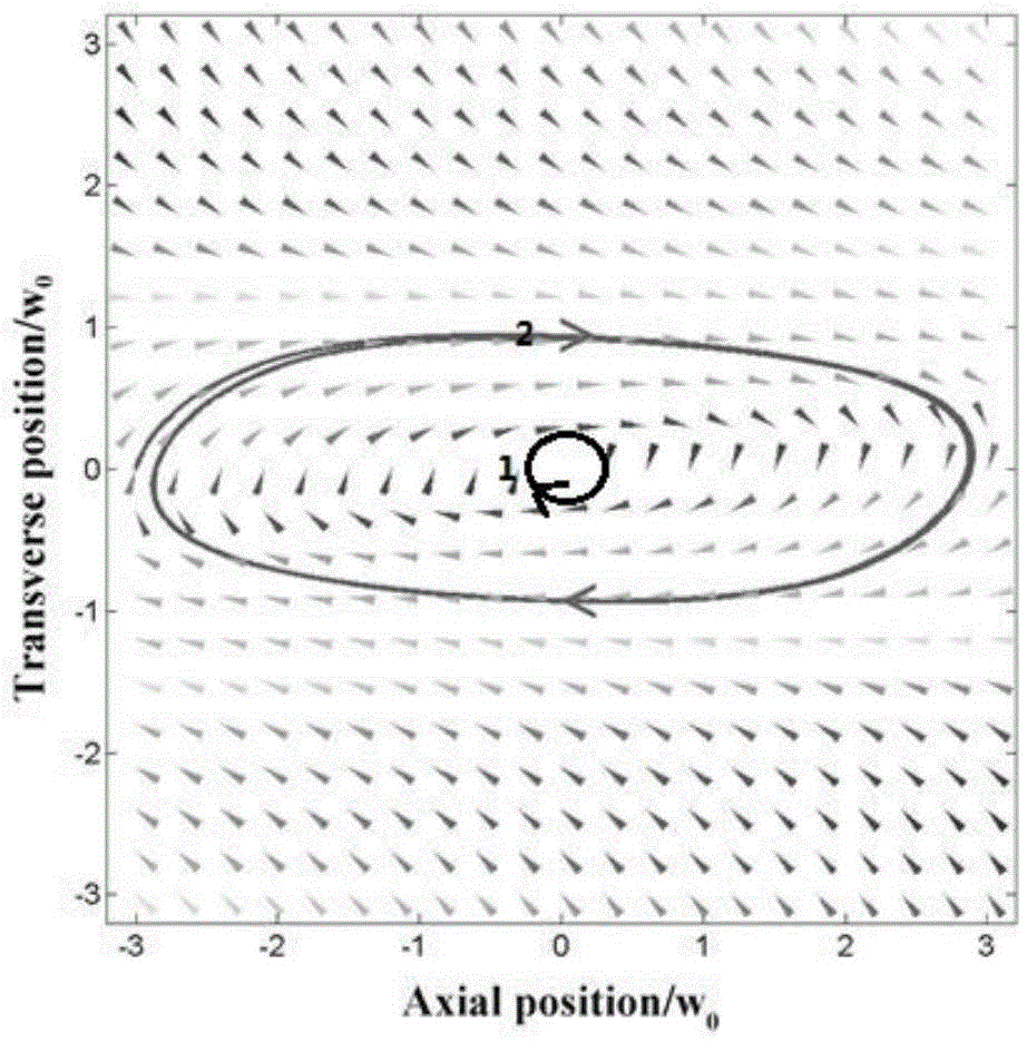
[0022] refer to figure 1 , the microparticles of the present invention are subjected to double-beam misalignment force field diagrams. In the figure, the triangular arrow represents the position of the microparticle, and the direction of the arrow represents the direction of the force. The closed curve 1 and the closed curve 2 both represent the rotational trajectory of the particle orbit.

[0023] The principle of the present invention is as follows: in the double-beam optical trap, the optical trapping force on the particle includes gradient force and scattering force, and the particle will be bound at the equilibrium position under the action of these two types of optical trapping force. Here the direction of the gradient force always points to the focal point of the trapping light bea...


PUM


Abstract

The invention belongs to the optical micromanipulation system technical field and relates to a device for realizing light-induced track rotation based on a double-light beam misalignment method and a method. The device is composed of two sets of capture light generating systems, a transparent sample pool, a lighting system and a measurement system; the lighting system and the measurement system are adopted as auxiliary systems, so that the rotation track of particles can be measured; the two sets of capture light generating systems are located at two sides of the transparent sample pool and respectively generate Gaussian beams with the same power; the Gaussian beams are inputted into the transparent sample pool from the two sides of the transparent sample pool and irradiate the particles along the tangential direction of the particles to be captured; the lighting system below the transparent sample pool is utilized to provide lighting; and the measurement system above the transparent sample pool is utilized to perform observation and measure the rotation track and rotation amplitude of the particles, and at same time, measure the track rotation speed of the particles. The device and the method have the advantages of high control precision, simple and convenient operation, simple experiment system and the like.

Description

technical field [0001] The invention belongs to the technical field of optical micro-manipulation systems, and in particular relates to a device and method for realizing photo-induced orbital rotation of mesoscopic particles based on a double-beam misalignment method. Background technique [0002] The mesoscopic scale refers to the scale between the microcosmic and the macroscopic and capable of maintaining quantum coherence. The size of the mesoscopic scale is related to the properties of materials and the physical environment, and is generally on the order of nm to μm. The motion of mesoscopic particles is one of the basic problems in physics and fluid mechanics. Controlling the motion of mesoscopic particles is very important for the research of biological cells, biomacromolecules and nanomotors, as well as the precise measurement of material properties in the microscopic field. significance. [0003] Photoinduced rotation is a mesoscopic-scale particle angle manipulatio...

Claims


Application Information

Patent Timeline
IPC IPC(8): G21K1/00
CPCG21K1/003G21K1/006
Inventor 肖光宗陈鑫麟刘坤山杨开勇罗晖
Owner NAT UNIV OF DEFENSE TECH
Why Eureka
Try Eureka