
An infrared detection method and detection equipment for automatic positioning detection position

A detection position and infrared detection technology, applied in the field of infrared detection, can solve the problems of low detection efficiency, inability to accurately locate and adjust the detection position and field of view, and inability to detect hidden defects and quality defects of components, so as to improve detection efficiency Effect

Active Publication Date: 2018-08-28
深圳市创科自动化控制技术有限公司
View PDF7 Cites 0 Cited by
  • Summary
  • Abstract
  • Description
  • Claims
  • Application Information

AI Technical Summary

Problems solved by technology

[0006] For this reason, the technical problem to be solved by the present invention is that the existing infrared detection devices and methods all use active infrared light sources, and the components to be detected are in a non-working state. Locate and adjust the detection position and field of view, and the detection efficiency is low, so an infrared detection device and detection method that can perform infrared detection when the component is working, can accurately locate and adjust the detection position and field of view, and has high detection efficiency

Method used


Image

  • An infrared detection method and detection equipment for automatic positioning detection position
  • An infrared detection method and detection equipment for automatic positioning detection position
  • An infrared detection method and detection equipment for automatic positioning detection position

Examples


Embodiment 1

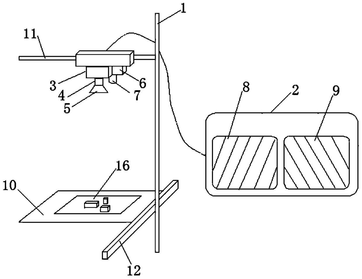
[0032] This embodiment provides an infrared detection device for automatically positioning and detecting a position, such as figure 1 shown, which includes,

[0033] Adjustable support 1, the adjustable support is an X-Y direction adjustment support, which is composed of an upper support 11 located at the top and a lower support 12 located at the lower part; the upper support 11 and the lower support 12 move along the horizontal plane, and the moving directions are mutually Vertical; the lower part of the adjustable support 1 is provided with a stage 10, and the sample 16 to be tested is placed on the stage 10;

[0034] The upper bracket 11 of the adjustable bracket 1 is connected with a visible light shooting device and an infrared light detection device; the visible light shooting device is composed of a visible light camera 3, a visible light lens 4 and a visible light light source 5 arranged on the visible light camera 3, The infrared light detection device is made up of ...

Embodiment 2

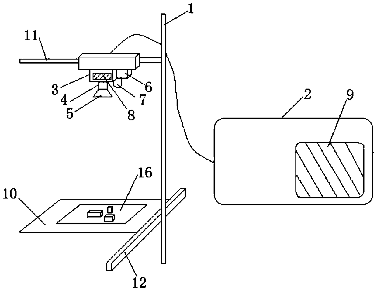
[0044] This embodiment provides an infrared detection device for automatically positioning and detecting a position, such as image 3 As shown, this embodiment is substantially the same as Embodiment 1, except that the positioning chip 8 integrated with visible light positioning software is set in the visible light camera 3, and the detection chip 9 integrated with infrared light detection software is set in the described In the control device 2.

Embodiment 3

[0046] This embodiment provides an infrared detection device for automatically positioning and detecting a position, such as Figure 4 As shown, this embodiment is substantially the same as Embodiment 1 and Embodiment 2, except that the positioning chip 8 integrated with visible light positioning software is arranged in the visible light camera 3, and the detection chip 9 integrated with infrared light detection software Set in the infrared camera 6.


PUM


Abstract

The invention discloses an infrared detecting method for automatically locating a detecting position and matched detecting equipment. A sample is detected in an electric work state, the actual position is firstly acquired through a visible light image, then an infrared temperature image of the sample to be detected is collected, the temperature difference area of the infrared temperature image and the background is compared and extracted, the area, temperature and position changes of the temperature difference area are observed and are finally compared with the reference value of a standard sample and a tolerant difference value, and a quality report of the sample is obtained. When the sample is in the electric work state, infrared radiation can be actively emitted, and hidden disadvantages and quality defects, shown after long-time running and work, of the sample can be detected. Meanwhile, in the detecting process, a key area can be concerned, a more precise infrared temperature image can be acquired, the detecting position and a detecting view field can be located and adjusted at any time, and detecting efficiency is improved.

Description

technical field [0001] The invention belongs to the technical field of infrared detection, and in particular relates to an infrared detection device and a detection method for automatically locating a detection position. Background technique [0002] Infrared detection is a method of detecting the surface of materials using the principle of infrared radiation. Its essence is to scan and record the temperature changes on the surface of the inspected material caused by defects or different thermal properties of the material. It is an important product quality inspection method. For example, according to the infrared and temperature performance of electronic products and components during operation, the stability and reliability of electronic products and components such as circuit boards can be analyzed and evaluated, and it can be used to detect debonding or debonding in glued or welded parts. Unpenetrated parts, defects such as cracks, voids and inclusions in solid materials...

Claims


Application Information

Patent Timeline
Patent Type & Authority Patents(China)
IPC IPC(8): G01N21/88G01N25/72
CPCG01N21/88G01N25/72
Inventor 沈奕鹏张宜飞黄剑
Owner 深圳市创科自动化控制技术有限公司
Learn More