
Ballscrew noise measuring method based on microphone array

A technology of ball screw pair and microphone array, which is applied in the direction of measuring devices, measuring ultrasonic/sonic/infrasonic waves, instruments, etc.

Active Publication Date: 2016-04-06
SOUTHEAST UNIV
View PDF7 Cites 1 Cited by
  • Summary
  • Abstract
  • Description
  • Claims
  • Application Information

AI Technical Summary

Problems solved by technology

[0006] In view of the above problems, the purpose of the present invention is to overcome the deficiencies in the existing noise measurement methods, and provide a method for measuring the radiation noise of the ball screw pair based on the microphone array

Method used


Image

  • Ballscrew noise measuring method based on microphone array
  • Ballscrew noise measuring method based on microphone array
  • Ballscrew noise measuring method based on microphone array

Examples


Embodiment Construction

[0045] The present invention will be described in detail below in conjunction with the accompanying drawings and embodiments.

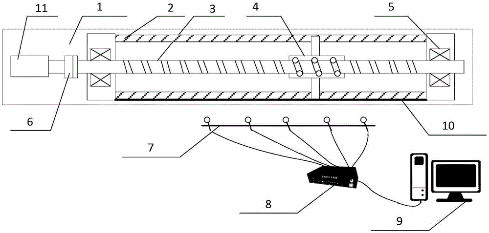
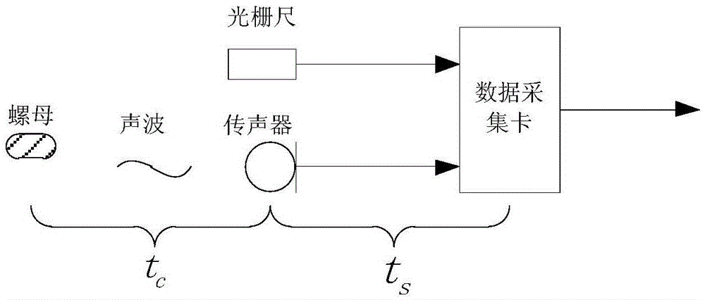
[0046] Such as figure 2As shown, 1 is the base of the test bench, 2 is the guide rail, 3 is the ball screw, 4 is the nut, 5 is the support bearing, 6 is the coupling, 7 is the microphone array, 8 is the data collector, 9 is the computer, 10 is a grating ruler, and 11 is a servo motor. The ball screw pair is installed on the comprehensive performance test bench, and M microphones form a uniform linear array, which is placed on one side of the test bench, parallel to the lead screw. The height of the microphone array is consistent with the nut, or slightly higher than the nut. The microphone array picks up the sound signal, and the grating ruler collects the position information of the nut, the sound-producing part of the ball screw pair. The main sources of interference at the noise measurement site are the noise of the servo motor and the noise of...


PUM


Abstract

The invention relates to a ballscrew noise measuring method based on a microphone array, and the method comprises the steps of processing a microphone array signal by a near field wave beam formation method; setting a weighting and a time delay coefficient according to object sound source position information to make the microphone array wave beam align at a nut position of the ballscrew always. In this way, the signal to noise ratio of noise measurement is improved. The method comprises the steps of installing the ballscrew on a comprehensive properties experiment table; arranging the microphone array close to the experiment table; collecting a microphone array signal and a nut position signal at the same time; synchronizing the array signal and the position; dividing a time domain signal into n segments; conducting near field wave beam formation processing to each segment; and synthesizing array signals of all segments to obtain the noise of the ballscrew.

Description

technical field [0001] The invention belongs to the field of radiation noise testing of high-speed precision transmission pairs, in particular to a method for measuring radiation noise of a ball screw pair based on a microphone array. Background technique [0002] The high-speed ball screw pair is one of the linear motion components representing the current world advanced level. As the execution unit of the CNC machine tool drive system, it plays a vital role in ensuring and improving the machining accuracy, work efficiency and comprehensive performance of the entire CNC machine tool. The improvement of modern CNC machine tool functions, the improvement of the level, and the characteristics of performance have been guaranteed by the innovative development and improvement of functional components. [0003] my country's rolling functional component industry represented by ball screw pairs started in the 1960s, and is an emerging industry that has gradually grown up with the d...

Claims


Application Information

Patent Timeline
IPC IPC(8): G01H17/00
CPCG01H17/00
Inventor 汤文成周建荣包达飞徐楠楠朱彦清
Owner SOUTHEAST UNIV
Learn More