
Side milling error compensation device based on non-extended straight-line surface and cutter spacing planning method of side milling error compensation device

An error compensation and side milling technology, which is applied in the field of side milling error compensation device and tool position planning, can solve problems such as failure to meet processing requirements, scrapped processed parts, wear of drive chain actuators, etc.

Inactive Publication Date: 2016-04-06
BEIJING INSTITUTE OF TECHNOLOGYGY
View PDF6 Cites 13 Cited by
  • Summary
  • Abstract
  • Description
  • Claims
  • Application Information

AI Technical Summary

Problems solved by technology

Due to the different directions of the normal vectors of the points on the straight generatrix, as long as a tool with a non-zero radius is used for side milling, overcut and undercut errors will inevitably occur, and during the machining process, due to the vibration, vibration, and There is a gap in the drive chain and the wear of the actuator will cause the tool movement to deviate from the ideal trajectory, resulting in machining errors. For non-developable ruled surfaces, these errors are fatal. scrapped parts

Method used


Image

  • Side milling error compensation device based on non-extended straight-line surface and cutter spacing planning method of side milling error compensation device
  • Side milling error compensation device based on non-extended straight-line surface and cutter spacing planning method of side milling error compensation device
  • Side milling error compensation device based on non-extended straight-line surface and cutter spacing planning method of side milling error compensation device

Examples


Embodiment 1

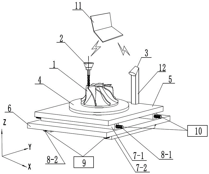
[0041] like figure 1As shown, a side milling error compensation device based on a non-developable ruled surface includes a chucking plate 4, a workpiece 1, and a milling cutter 2 arranged above the workpiece 1 for side milling. On the chuck 4, it is characterized in that: it also includes a three-dimensional scanner 3, a microcomputer 11, a column 12 and a knife position compensation mechanism, and the knife position compensation mechanism is arranged below the chucking disc 4; the knife position compensation mechanism includes: the first A translation platform 5, a second translation platform 6, a first nut pair 7-1, a first leading screw 8-1, a second nut pair 7-2, a second leading screw 8-2, a first servo motor 9 and a first screw Two servo motors 10; the first nut pair 7-1 is arranged below the first translation platform 5, the first screw 8-1 cooperates with the first nut pair 7-1 through balls, and the first screw The rod 8-1 is connected to the output end of the first ...

Embodiment 2

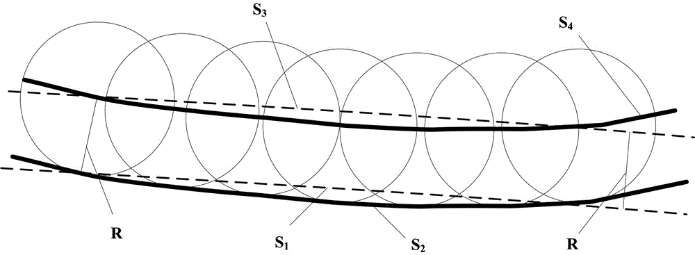
[0046] Because the non-developable ruled surface is characterized by the different normal vector directions of points on the straight generatrix, any tool with a non-zero radius will have a theoretical error in side milling, and the tool envelope cannot be completely tangent to the design surface. For the side milling of this curved surface, surface approximation processing is used, such as figure 2 As shown, the tool position planning of non-developable ruled surface in side milling mainly includes: design surface S1, tool envelope surface S2, equidistant surface S3 of design surface, tool axis trajectory surface S4, milling cutter envelope surface and tool axis The trajectory surface is a pair of equidistant surfaces. According to the range invariance under isometric mapping in differential geometry, the range between the tool envelope surface and the design surface is equal to the range between the tool axis trajectory surface and the design surface equidistant surface , s...


PUM


Abstract

The invention relates to the field of machining, in particular to a side milling error compensation device based on a non-extended straight-line surface and a cutter spacing planning method of the side milling error compensation device. The side milling error compensation device comprises a clamping disc, a workpiece and a milling cutter arranged above the workpiece and used for side milling, and the workpiece is arranged on the clamping disc. The side milling error compensation device is characterized by further comprising a three-dimensional scanner, a microcomputer, a stand column and a cutter spacing compensation mechanism; the cutter spacing compensation mechanism is arranged below the clamping disc; a non-extended straight-line surface five-axis side milling cutter path is planned by adopting a four-point offset manner, whether interference exists or not is judged in real time in an online manner, online adjustment is performed according to the judging result, collision in the machining process is avoided while the machining error is reduced, and the purpose of rapid and efficient machining is achieved; and the generated cutter spacing is further optimized and completed in cooperation with the error compensation device, and the error is further lowered.

Description

technical field [0001] The invention relates to the field of mechanical processing, in particular to a side milling error compensation device based on a non-developable ruled surface and a tool position planning method thereof. Background technique [0002] A non-developable ruled surface is formed by sweeping a straight generatrix along a wire, and is non-developable. Discrete the surface can obtain multiple straight lines with different directions on the surface. Due to the different directions of the normal vectors of the points on the straight generatrix, as long as a tool with a non-zero radius is used for side milling, overcut and undercut errors will inevitably occur, and during the machining process, due to the vibration, vibration, and There is a gap in the drive chain and the wear of the actuator will cause the tool movement to deviate from the ideal trajectory, resulting in machining errors. For non-developable ruled surfaces, these errors are fatal. Part scrappe...

Claims


Application Information

Patent Timeline
Patent Type & Authority Applications(China)
IPC IPC(8): B23C3/16B23Q15/12
CPCB23C3/16B23Q15/12
Inventor 刘志兵严涛王东前王西彬闫正虎刘彪
Owner BEIJING INSTITUTE OF TECHNOLOGYGY
Learn More