
Roller grinding and grinding method of main drive grinding roller friction drive grinding disc

A technology of friction transmission and main transmission, which is applied in the powder preparation, metallurgy, and mining fields of the building materials industry. It can solve the problems of difficulty in manufacturing special reducers and motors, increase the energy consumption of the grinding system, and increase manufacturing costs. Effects of safe operation rate, height reduction, and operating cost reduction

Active Publication Date: 2018-06-19
NANJING JULI INTELLIGENT MFG TECH INST CO LTD
View PDF10 Cites 0 Cited by
  • Summary
  • Abstract
  • Description
  • Claims
  • Application Information

AI Technical Summary

Problems solved by technology

Because the reducer of this kind of roller mill needs to transmit power and bear the heavy load of grinding pressure, it is necessary to design a special reducer for roller mill. The production cost is several times that of ordinary reducer. It is required to increase the production scale, increase the size of the grinding disc, and the number of grinding rollers on the grinding disc has tended to be four or six. One grinding disc drives multiple grinding rollers to rotate by themselves through friction. Therefore, it is difficult to manufacture the special reducer and motor that needs to be configured, and the cost is high. high, which becomes the bottleneck of the large-scale roller mill, and because the special reducer is arranged under the grinding table, the height of the grinding roller, the pressure device, the shell and the entire roller mill system associated with it have to be increased, which not only aggravates the manufacturing process cost, while increasing the energy consumption of the grinding system

Method used


Image

  • Roller grinding and grinding method of main drive grinding roller friction drive grinding disc
  • Roller grinding and grinding method of main drive grinding roller friction drive grinding disc

Examples


Embodiment Construction

[0026] The following will clearly and completely describe the technical solutions in the embodiments of the present invention with reference to the accompanying drawings in the embodiments of the present invention. Obviously, the described embodiments are only some, not all, embodiments of the present invention. Based on the embodiments of the present invention, all other embodiments obtained by persons of ordinary skill in the art without creative efforts fall within the protection scope of the present invention.

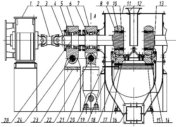
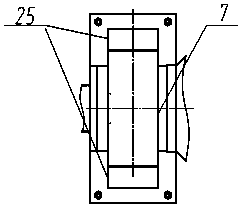
[0027] Such as figure 1 As shown, the roller mill of the grinding roller friction transmission grinding disc includes: a grinding roller device 28, a grinding roller transmission device 1, a universal coupling 2, a pressurizing device 21, a hinge support device 23, a deflection stop device 25, and a grinding disc 14 , disc liner 13, disc supporting device 18;

[0028] The roller grinding device includes: a roller shaft 3, a roller sleeve 8, a pressurized bearing g...


PUM


Abstract

The invention provides a roller mill with a main drive grinding roller driving a grinding disc in a friction manner and a grinding method of the roller mill. The roller mill comprises a grinding roller device, a grinding roller drive device, a universal coupling, a pressurizing device, a hinge supporting device, the grinding disc and a grinding disc supporting device, wherein a part, which extends out of a hinge support bearing block, of the rear end of a roller shaft of the grinding roller device is flexibly connected with the grinding roller drive device through the universal coupling; roller shells of the grinding roller device are uniformly distributed above the grinding disc in the peripheral direction and are in contact with materials to be ground on a grinding disc lining plate; hydraulic pressure of the pressurizing device is transmitted to the grinding disc and the materials on the grinding disc through a pressurizing bearing block, a pressurizing bearing pack, the roller shaft and the roller shells; and torque of the main drive roller shaft is transmitted to the grinding disc through a friction force of the materials and drives the grinding disc to rotate around the axis of the grinding disc. Compared with an existing roller mill technology, the roller mill remarkably reduces manufacturing cost and operation cost; energy-saving grinding is implemented; and meanwhile, the manufacturing bottleneck of a special speed reducer for a large roller mill is eliminated.

Description

technical field [0001] The invention belongs to the technical field of grinding engineering equipment, and is mainly applied to powder preparation in mining, metallurgy and building material industries. Background technique [0002] The roller mills of the current technology are all driven by the transmission system to drive the grinding disc. The material fed to the grinding disc is crushed by a group of grinding rollers during the process of rotating and centrifugally moving with the grinding disc, and drives a group of grinding rollers through the friction of the crushed material. The rollers rotate on their own. Because the reducer of this kind of roller mill needs to transmit power and bear the heavy load of grinding pressure, it is necessary to design a special reducer for roller mill. The production cost is several times that of ordinary reducer. It is required to increase the production scale, increase the size of the grinding disc, and the number of grinding roller...

Claims


Application Information

Patent Timeline
Patent Type & Authority Patents(China)
IPC IPC(8): B02C15/14
CPCB02C15/14
Inventor 曹卫倪文龙查文炜
Owner NANJING JULI INTELLIGENT MFG TECH INST CO LTD
Learn More