Test device for applying axial tensile load to concrete members

A technology of axial tension and test equipment, applied in the direction of applying stable tension/pressure to test material strength, material inspection products, etc., to achieve the effect of easy control of load size, simple operation, and avoiding fracture and separation

Active Publication Date: 2018-05-08
ZHEJIANG UNIV OF TECH
View PDF8 Cites 0 Cited by
  • Summary
  • Abstract
  • Description
  • Claims
  • Application Information

AI Technical Summary

Problems solved by technology

[0006] In order to overcome the problems of the existing concrete member axial tension load loading method, the present invention provides a small volume, simple operation, reliable method and low cost, which is convenient for concrete members to apply axial tensile load, and can be in erosion together with the concrete member Apparatus for applying axial tensile loads to concrete members subjected to media erosion tests

Method used


Image

  • Test device for applying axial tensile load to concrete members
  • Test device for applying axial tensile load to concrete members
  • Test device for applying axial tensile load to concrete members

Examples


Embodiment 1

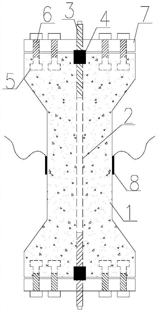
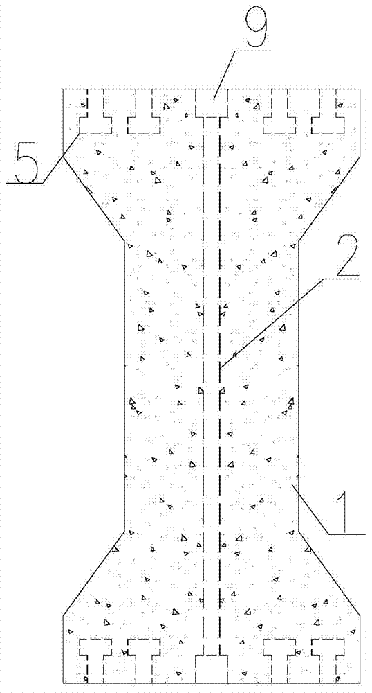
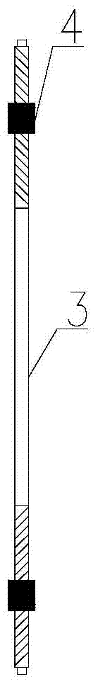
[0028] Embodiment 1 A test device for applying an axial tensile load to a concrete member according to the present invention, comprising a concrete axial tensile test piece 1, a load-bearing steel plate 7 mounted on both ends of the concrete axial tensile test piece, and a T-shaped embedded part with internal threads 5. Loading the screw rod 3 and the strain gauge 8, the concrete axial tension test piece 1 is provided with reserved through holes 2 arranged in the axial direction, and the two ends of the concrete axial tension test piece 1 are respectively embedded with multiple T-shaped Embedded part 5, and the threaded section of the T-shaped embedded part 5 points to the outside of the concrete axial tension test piece 1; the bearing screw 3 runs through the reserved through hole 2, and is arranged at both ends of the bearing screw 3 Nut 4, the outer side of the nut 4 is equipped with a load-bearing steel plate 7, and the threaded section of the T-shaped embedded part 5 is sc...

Embodiment 2

[0037] Embodiment 2 With measuring water-cement ratio 0.53 below, mixing ratio is cement: water: sand: the concrete of coarse aggregate=1:0.53:2.0:3.0 is example under the axial tensile load action chlorine salt transmission process, to the present invention The work is described in detail.

[0038]The raw materials for mixing concrete in this embodiment are: the cement is P.I 525 grade Portland cement, the sand is river sand with a fineness modulus of 2.6, the coarse aggregate is continuously graded crushed stone (maximum particle size 25mm), and the water is Tap water. The effective section size of the shaft-pulled concrete specimen is 100mm × 100mm, the flange protrusion length is 50mm, the flange edge height is 100mm, and the specimen length is 1000mm. For the embedded part, a reserved through hole 2 with a diameter of 26mm is reserved in the center of the test piece. After pouring and forming, the standard curing in the curing room is 28d, and the number of test pieces i...


PUM


Abstract

A test device for applying axial tensile loads to concrete members, including concrete axial tension specimens, load-bearing steel plates installed at both ends of the concrete axial tension specimens, T-shaped embedded parts with internal threads, load-bearing screws and strain gauges, concrete axial tension specimens The test piece is provided with reserved through holes arranged in the axial direction, and multiple T-shaped embedded parts are pre-embedded at both ends of the concrete axial tension test piece, and the threaded section of the T-shaped embedded parts points to the outside of the concrete axial tension test piece; Through the reserved through holes, nuts are arranged at both ends of the load-bearing screw, and the outside of the nut is equipped with a load-bearing steel plate. The threaded section of the T-shaped embedded part is screwed with the fastening bolt; the strain gauge is installed on the side wall of the concrete axial tension test piece. The signal output terminal of the strain gauge is electrically connected with the external strain gauge. The beneficial effects of the present invention are mainly manifested in: the loading device can overcome the difficulty of applying axial load, the operation is simple, the cost is low, it does not rust, and can be reused; The size is easy to control.

Description

technical field [0001] The invention relates to a test device for applying axial tensile load to a concrete member. Background technique [0002] Concrete structures in service work under the joint action of load and environment, and the research results of concrete durability under no load cannot reasonably reflect the actual state of the structure. Concrete structures are often subjected to erosion such as seawater, deicing salt, and carbon dioxide while bearing loads. Under the coupling effects of load and environmental factors or multiple factors, concrete structures often fail before reaching the design life. The huge economic loss and casualties caused by it have aroused widespread concern both at home and abroad. Concrete is a typical porous material, and the corrosive medium invades the interior of the concrete through the pores of the concrete, which leads to corrosion of steel bars and cracking of the concrete protective layer, which in turn affects the service pe...

Claims


Application Information

Patent Timeline
Patent Type & Authority Patents(China)
IPC IPC(8): G01N3/08G01N33/38
Inventor 付传清闫东明金南国裴华富
Owner ZHEJIANG UNIV OF TECH
Why Eureka
Try Eureka