Precise composite molding grinding machine for numerical control linear guide rail

A compound molding and linear guide rail technology, which is applied in the direction of grinding machines, grinding bed, portal grinding machine tools, etc., can solve the problem of motion distortion accuracy affecting the motion distortion accuracy of linear guide rail, large center distance between vertical and horizontal grinding heads, structural influence, etc. problems, to achieve the effect of improving processing efficiency, improving grinding accuracy and reducing impact

Inactive Publication Date: 2016-03-23
JIANGMEN INTIN NUMERICAL CONTROL MACHINE TOOL CO LTD
View PDF6 Cites 9 Cited by
  • Summary
  • Abstract
  • Description
  • Claims
  • Application Information

AI Technical Summary

Problems solved by technology

In the prior art, most guide rail grinding machines use two grinding heads. Generally, after the bottom surface of the guide rail is ground, it is installed on the workbench, and then the two sides of the guide rail are processed. The overall length error and installation error of the machine tool directly affect the linear guide rail pair. At the same time, even if three grinding heads are used, affected by the structure of the machine tool, or...

Method used


Image

  • Precise composite molding grinding machine for numerical control linear guide rail
  • Precise composite molding grinding machine for numerical control linear guide rail
  • Precise composite molding grinding machine for numerical control linear guide rail

Examples


Embodiment Construction

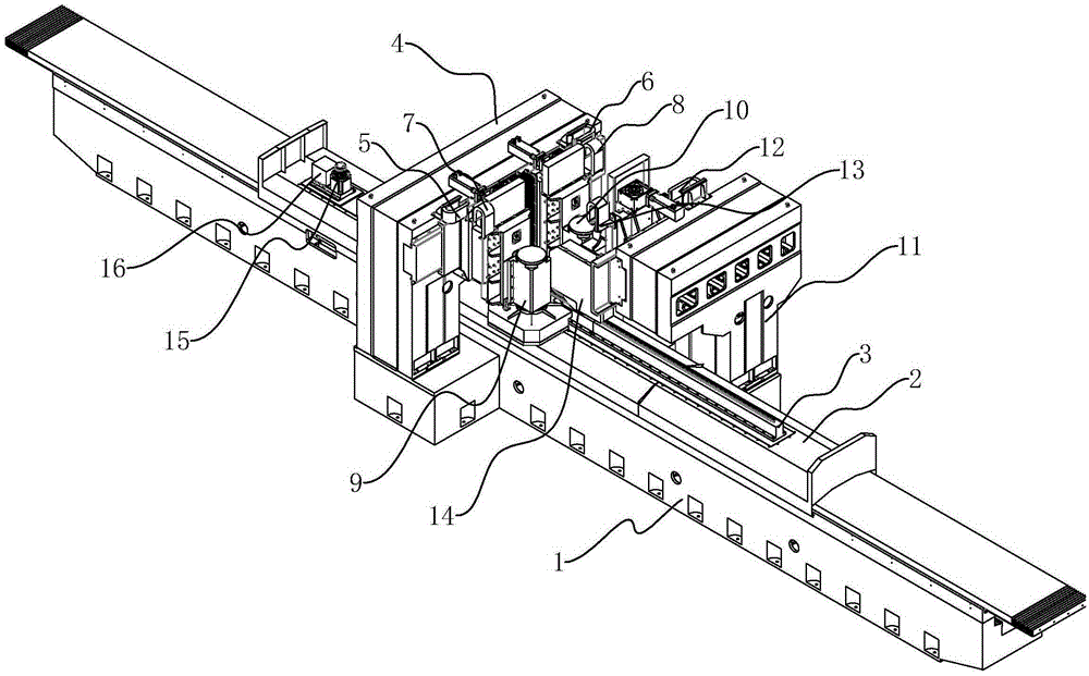
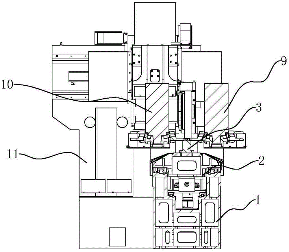
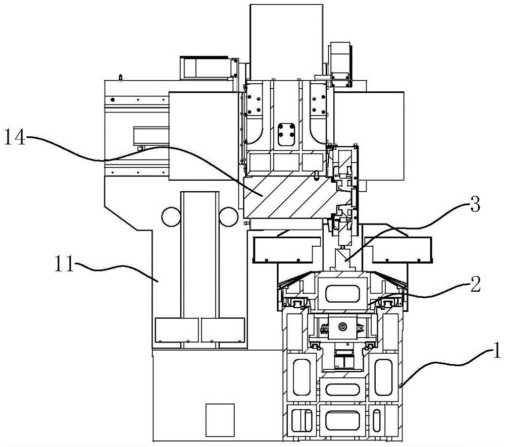
[0013] refer to Figure 1 to Figure 3 , a numerically controlled linear guide rail precision compound molding grinding machine of the present invention, comprising a U-shaped base 1, on which an embedded grinding table 2 driven by a driving device and capable of longitudinal and horizontal movement is arranged, the A magnetic fixture 3 for fixing the guide rail is installed on the embedded grinding table 2, a gantry 4 is arranged above the U-shaped base 1, and the first and second transverse drive mechanisms 5 and 6 are installed on the gantry beam respectively, and the second 1. The first and second vertical grinding head mechanisms 9 and 10 are installed on the second transverse drive mechanism 5 and 6 respectively through the first and second vertical drive mechanisms 7 and 8, and the front of the gantry 4 is provided with a vertical Type supporting frame 11, the third horizontal driving mechanism 12 is installed on this vertical supporting frame 11, and the third horizonta...


PUM


Abstract

The invention discloses a precise composite molding grinding machine for a numerical control linear guide rail. The precise composite molding grinding machine comprises a U-shaped base. The U-shaped base is provided with an embedded grinding workbench which is driven by a drive device and can horizontally move in the longitudinal direction. The embedded grinding workbench is provided with a magnetic clamp used for fixing the guide rail. A portal frame is arranged above the U-shaped base. A beam of the portal frame is provided with a first transverse drive mechanism and a second transverse drive mechanism. The first transverse drive mechanism is connected with a first vertical grinding head mechanism through a first vertical drive mechanism, and the second transverse drive mechanism is connected with a second vertical grinding head mechanism through a second vertical drive mechanism. A vertical bearing frame is arranged in front of the portal frame and provided with a third transverse drive mechanism. The third transverse drive mechanism is connected with a horizontal grinding head mechanism through a third vertical drive mechanism. Due to the fact that the first vertical grinding head mechanism, the second vertical grinding mechanism and the horizontal grinding head mechanism are used for grinding the two side faces and the installing bottom face of the guide rail at the same time, workpieces do not need to be clamped many times, the machining efficiency and the grinding precision can be greatly improved, and the product quality is guaranteed.

Description

technical field [0001] The invention relates to a grinding machine, in particular to a linear guide grinding machine. Background technique [0002] In the production process of the linear guide rail, it is necessary to use a guide rail grinder to grind the two sides, the raceway surface and the installation bottom surface of the linear guide rail. In the prior art, most guide rail grinding machines use two grinding heads. Generally, after the bottom surface of the guide rail is ground, it is installed on the workbench, and then the two sides of the guide rail are processed. The overall length error and installation error of the machine tool directly affect the linear guide rail pair. At the same time, even if three grinding heads are used, affected by the structure of the machine tool, or the horizontal grinding head does not use an independent column, or the distance between the fixture surface of the linear guide rail and the guide rail surface of the worktable is relative...

Claims


Application Information

Patent Timeline
IPC IPC(8): B24B7/14B24B7/00B24B7/06B24B27/00B24B41/02B24B47/16
CPCB24B7/14B24B7/005B24B7/06B24B27/0076B24B41/02B24B47/16
Inventor 唐兵仿彭雨田蔡沙李志坚郭政威唐浩
Owner JIANGMEN INTIN NUMERICAL CONTROL MACHINE TOOL CO LTD
Why Eureka
Try Eureka