A processing method of blade tenon with asymmetric pressure surface

A blade tenon and processing method technology, applied in metal processing, metal processing equipment, metal processing machine parts, etc., can solve problems such as difficulty in improving production efficiency, affecting processing quality, and occurrence of waste products, reducing skill requirements and reducing tool setting. Workload, quick knife setting effect

Active Publication Date: 2017-11-10
AECC AERO SCI & TECH CO LTD
View PDF7 Cites 0 Cited by
  • Summary
  • Abstract
  • Description
  • Claims
  • Application Information

AI Technical Summary

Problems solved by technology

It is very difficult to process the tenon of this kind of blade, and it is necessary to use a forming milling cutter for milling. However, because the existing forming milling cutter does not have a tool setting structure, the difficulty of milling is tool setting. If the tool setting is not accurate, It is bound to affect the processing quality, and even produce waste products
Using the existing forming milling cutter and the existing tool setting method, it will take a long time to complete the tool setting even for skilled technicians, so it is difficult to improve production efficiency

Method used


Image

  • A processing method of blade tenon with asymmetric pressure surface
  • A processing method of blade tenon with asymmetric pressure surface
  • A processing method of blade tenon with asymmetric pressure surface

Examples


Embodiment Construction

[0034] The processing method of the blade tenon with asymmetric pressure surface according to the present invention will be further described below through examples and in conjunction with the accompanying drawings.

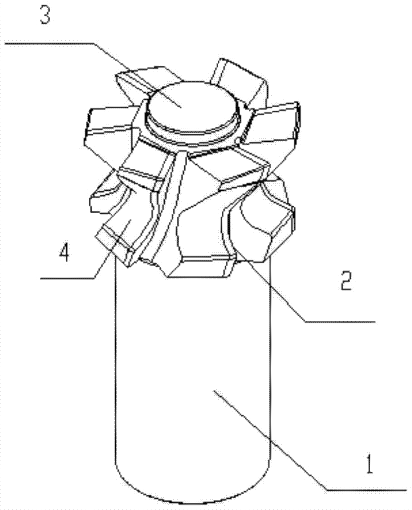
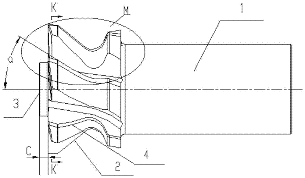
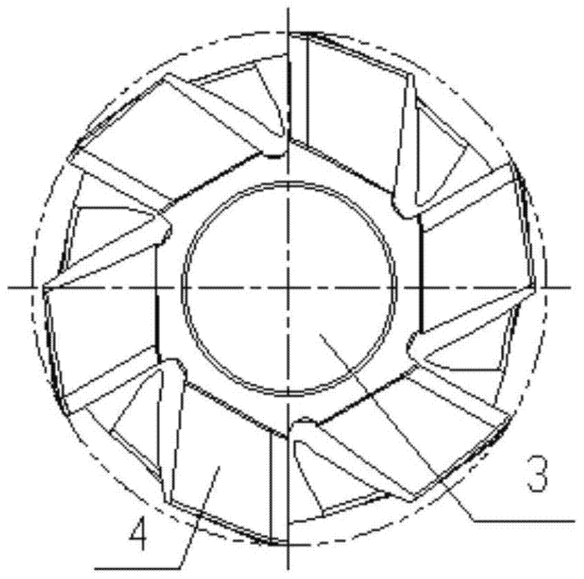
[0035] Processing in this example Figure 6 The blade tenon 5 with an asymmetrical pressure surface is shown. The material of the blade tenon is stainless steel. The angle between the basin pressure surface 5-5 of the blade tenon and the centerline 5-1 of the blade profile is 37°. The blade tenon The angle between the back pressure surface 5-6 and the centerline 5-1 of the blade profile is 33°, and the distance between the lowest point of the bottom surface of the blade tenon and the blade tenon reference line 5-2 is H=17.12mm.

[0036] In this embodiment, the first forming milling cutter with a tool setting structure and the second forming milling cutter with a tool setting structure are used for milling on a CNC milling machine, and the model of the CNC milling ...


PUM


Abstract

The invention relates to a machining method for a blade rabbet with asymmetric pressure faces. A first formed cutter with a cutter setting structure and a second formed cutter with a cutter setting structure are used on a numerical control milling machine to conduct milling, the two formed cutters with the cutter setting structures are each composed of a cutter bar, a cutter tooth disc and a cutter setting table; and each cutter bar, the corresponding cutter tooth disc and the corresponding cutter setting table are sequentially connected to be of an integrated structure. The machining method includes the following steps: (1) the surface of one side of the back pressure face of the blade rabbet is machined with the first formed cutter with the cutter setting structure; and (2) the surface of one side of the basin pressure face of the blade rabbet is machined with the second formed cutter with the cutter setting structure. By means of the two steps, a rectangular coordinate system is built with the center line of the blade form of a blade serving as a Z axis during cutter setting and the datum line of the blade rabbet with the asymmetric pressure faces serving as a Y axis, the lowest position of the bottom face of the blade rabbet with the asymmetric pressure faces serves as the cutter setting position, and the cutter setting end face of the two formed cutters with the cutter setting structures serves as a cutter setting standard face.

Description

technical field [0001] The invention belongs to a processing method for an engine blade tenon, in particular to a processing method for a blade tenon with an asymmetric pressure surface. Background technique [0002] The blade tenon of the engine has various structural forms. The blade tenon with an asymmetric pressure surface means that the angle between the pressure surface of the blade tenon and the center line of the blade profile is not equal to the angle between the back pressure surface of the blade tenon and the blade profile. The angle between the centerlines (see Figure 6 ). It is very difficult to process the tenon of this kind of blade, and it is necessary to use a forming milling cutter for milling. However, because the existing forming milling cutter does not have a tool setting structure, the difficulty of milling is tool setting. If the tool setting is not accurate, It is bound to affect the processing quality and even produce waste products. Using the exi...

Claims


Application Information

Patent Timeline
Patent Type & Authority Patents(China)
IPC IPC(8): B23C3/16B23C5/12B23Q15/22
CPCB23C3/16B23C5/12B23Q15/22
Inventor 罗培真李惠邓杰郝凯江龙张容
Owner AECC AERO SCI & TECH CO LTD
Why Eureka
Try Eureka