A form milling cutter with tool setting structure

A technology for forming milling cutters and tool setting tables, which is applied to milling cutters, milling machine equipment, and details of milling machine equipment. It can solve problems that affect processing efficiency, difficulty in tool setting, and difficult machining quality, so as to reduce skill requirements and reduce tool setting. The effect of reducing the workload and reducing the tool setting time

Active Publication Date: 2017-12-12
AECC AERO SCI & TECH CO LTD
View PDF10 Cites 0 Cited by
  • Summary
  • Abstract
  • Description
  • Claims
  • Application Information

AI Technical Summary

Problems solved by technology

Although the existing forming milling cutters have various structures, since there is no tool setting structure, it is difficult to set the tool when processing some structurally asymmetric parts (such as the asymmetric tenon of the pressure surface of the blade), which not only affects the processing efficiency, And it is difficult to guarantee the processing quality

Method used


Image

  • A form milling cutter with tool setting structure
  • A form milling cutter with tool setting structure
  • A form milling cutter with tool setting structure

Examples


Embodiment Construction

[0022] The form milling cutter with tool setting structure of the present invention will be further described below through examples and with reference to the accompanying drawings.

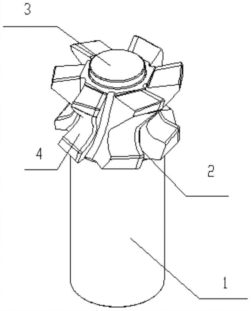
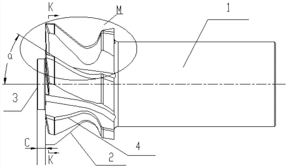
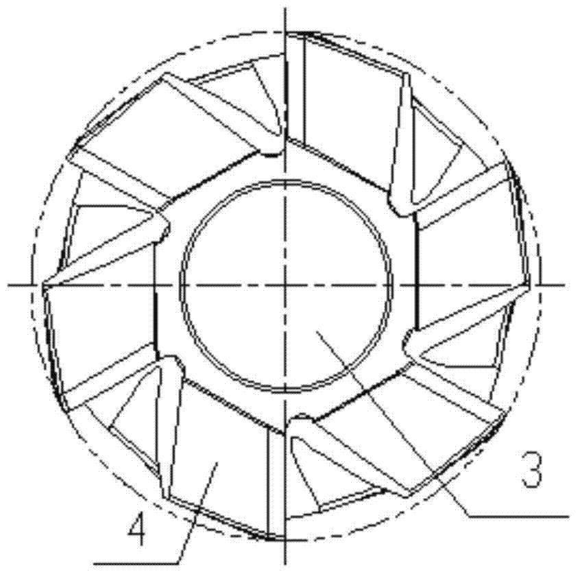
[0023] In this embodiment, the forming milling cutter with tool setting structure is as figure 1 , figure 2 , image 3 As shown, it consists of a cutter bar 1, a cutter disc 4 and a tool setting table 3. The cutter bar 1 is cylindrical, and the cutter disc 4 is provided with six cutter teeth, and each cutter tooth surrounds the cutter disc 4 The center lines of the center lines are equiangularly distributed. The tool setting table 3 is in the shape of a truncated cone. The center lines of the tool rest 3 are the same straight line.

[0024] The form milling cutter with tool setting structure in this embodiment is used for processing Image 6 The blade tenon 5 with an asymmetrical pressure surface is shown. The material of the blade tenon is stainless steel. The angle between the basin pressu...


PUM


Abstract

A forming milling cutter with a tool setting structure, which is composed of a cutter bar, a cutter disc and a tool setting table, the cutter bar is cylindrical, and at least three cutter teeth are arranged on the cutter disc, and each cutter The center lines of the tooth discs are equiangularly distributed, and the cutting edge profile of each tooth matches the shape of the workpiece to be processed and is a helical line. The tool setting table is in the shape of a conical cone. The tables are connected in turn and are an integrated structure, and the centerlines of the tool bar, the cutter disc, and the tool setting table are the same straight line. When in use, the end face of the tool setting table is used as the tool setting reference plane to determine the position of the workpiece to be processed, so that rapid tool setting can be realized. Compared with the existing forming milling cutter, the tool setting time can be reduced by 80% in the tool setting process about.

Description

technical field [0001] The invention belongs to a forming milling cutter, in particular to a forming milling cutter which is convenient for tool setting. Background technique [0002] Forming milling cutters are mainly used to process grooved parts with complex shapes. Using forming milling cutters to process parts can form the surface of parts at one time. It has been widely used in production. Although the existing forming milling cutters have various structures, since there is no tool setting structure, it is difficult to set the tool when processing some structurally asymmetric parts (such as the asymmetric tenon of the pressure surface of the blade), which not only affects the processing efficiency, And it is difficult to guarantee the processing quality. SUMMARY OF THE INVENTION [0003] The purpose of the present invention is to overcome the deficiencies of the prior art, and provide a form milling cutter with a tool setting structure, so as to realize fast tool s...

Claims


Application Information

Patent Timeline
Patent Type & Authority Patents(China)
IPC IPC(8): B23C5/12B23C3/18
Inventor 罗培真李惠邓杰郝凯江龙张容
Owner AECC AERO SCI & TECH CO LTD
Why Eureka
Try Eureka