
Flow-divided cutting fluid filter unit

A filter device and cutting fluid technology, applied in the direction of filtration separation, membrane filter, mobile filter element filter, etc., can solve the problems of reduced utilization rate of cutting fluid, poor filtering effect, waste of filter net, etc., to promote flow and Filter, improve filter effect, keep clean effect

Active Publication Date: 2016-03-23
南通东晨重型机床有限公司
View PDF7 Cites 15 Cited by
  • Summary
  • Abstract
  • Description
  • Claims
  • Application Information

AI Technical Summary

Problems solved by technology

The existing cutting fluid filtering device has complex structure and poor filtering effect, which greatly reduces the utilization rate of cutting fluid
[0004] Now the filter is generally used for filtering, the cutting fluid poured into the casing from the feed port can only flow to the part of the filter, the filtering effect is not good, and at the same time, other parts of the filter are wasted

Method used


Image

  • Flow-divided cutting fluid filter unit

Examples


Embodiment Construction

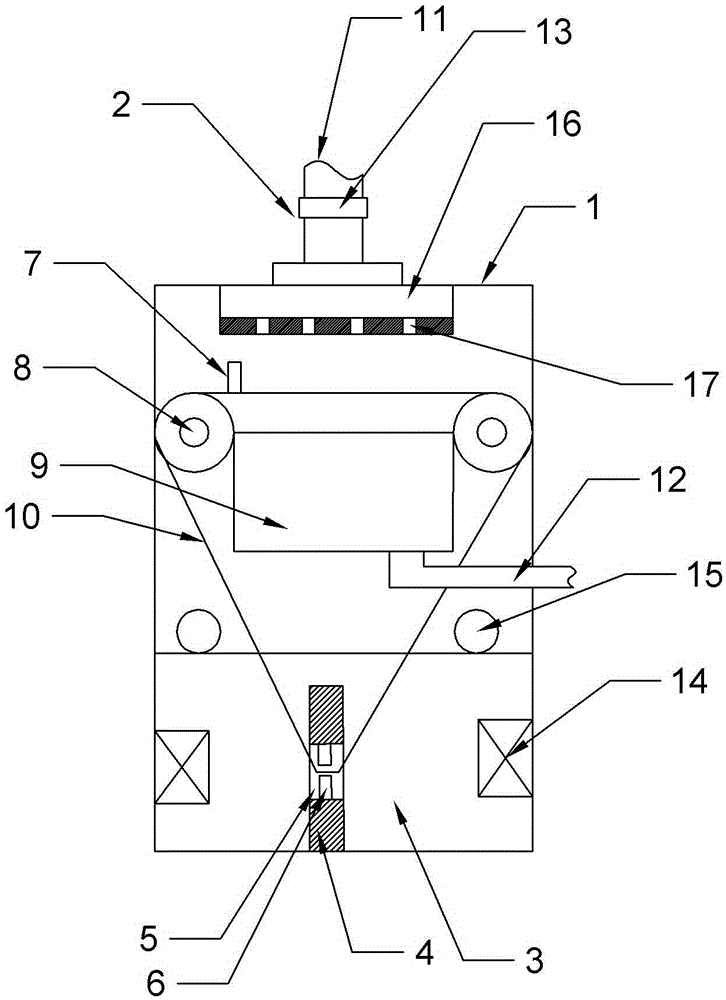
[0015] Such as figure 1 As shown, the split-flow cutting fluid filtering device includes a casing 1, a filtering mechanism and a cleaning mechanism. The filtering mechanism is located in the casing 1, and the cleaning mechanism is located below the filtering mechanism. 2. A diversion plate 16 is arranged on the lower surface, and a plurality of diversion holes 17 are arranged on the lower surface of the diversion plate 16. The cleaning mechanism includes a cleaning tank 3 and a cleaning block 4. The cleaning block 4 is vertically arranged at the bottom of the cleaning tank 3. A horizontal through hole 5 is arranged in the middle of the cleaning block 4. The upper and lower surfaces of the through hole 5 are oppositely provided with a scraper 6. The filter mechanism includes a scraper 7, two drums 8, a collection tank 9 and a filter screen 10, the two drums 8 are symmetrically located on both sides of the casing 1, the filter screen 10 includes a filter section and a cleaning s...


PUM


Abstract

The invention relates to the field of cutting fluid processing, in particular to a flow-divided cutting fluid filter unit, comprising an enclosure, a filtering mechanism and a cleaning mechanism, wherein the filtering mechanism is located in the enclosure, the cleaning mechanism is located below the filtering mechanism, the upper end of the enclosure is provided with a feed inlet, a flow dividing plate is arranged below the feed inlet, and the lower end face of the flow dividing plate is provided with multiple flow dividing holes; the cleaning mechanism comprises a cleaning groove and a cleaning block, the cleaning block is vertically arranged at the bottom of the cleaning groove, the middle of the cleaning block is provided with a through hole in the horizontal direction, and the upper and lower surfaces of the through hole are oppositely provided with scraping knifes; the filtering mechanism comprises a scraper blade, two rollers, a collecting tank and a filtering net, the two rollers are symmetrically located at two sides in the enclosure, the filtering net comprises a filtering section and a cleaning section, the filtering section is located between the two rollers, the cleaning section passes through the through hole, the cleaning section and the filtering section form a closed annular structure, the collecting tank is located right below the filtering section, the scraper blade is located right above the filtering section, and the lower end face of the scraper blade is clung to the upper surface of the filtering section. By adopting the flow-divided cutting fluid filter unit, the feed inlet can perform flow dividing on cutting fluid, so that the cutting fluid is evenly distributed on the filtering net, and blocking is prevented.

Description

technical field [0001] The invention relates to the field of glass processing, in particular to a split-flow cutting fluid filtering device. Background technique [0002] Metal cutting fluid (referred to as cutting fluid) has a lubricating effect during the cutting process, which can reduce the friction between the rake face and chips, the flank face and the machined surface, and form a part of the lubricating film, thereby reducing the cutting force, friction and Power consumption, reduce the surface temperature and tool wear of the friction part between the tool and the workpiece blank, and improve the cutting performance of the workpiece material; the cutting fluid also has a cooling effect, through the cutting fluid and the tool (or grinding wheel) heated by cutting, chips and workpiece The convection and vaporization between the cutting heat is taken away from the tool and the workpiece, thereby effectively reducing the cutting temperature, reducing the thermal deformat...

Claims


Application Information

Patent Timeline
IPC IPC(8): B01D33/04B01D33/44B01D33/46B01D33/80
CPCB01D33/00B01D33/44B01D33/46B01D33/466B01D33/80B01D2201/085
Inventor 朱静
Owner 南通东晨重型机床有限公司
Learn More