
Realization method based on unification of heat-force-electromagnetic field network

An implementation method and electromagnetic field technology, applied in the direction of electrical digital data processing, special data processing applications, instruments, etc., can solve the problems of small amount of calculation, inaccurate calculation of thermal radiation, and inability to realize one-to-one correspondence

Active Publication Date: 2016-03-16
NO 32 RES INST OF CHINA ELECTRONICS TECH GRP
View PDF3 Cites 4 Cited by
  • Summary
  • Abstract
  • Description
  • Claims
  • Application Information

AI Technical Summary

Problems solved by technology

Therefore, the two cannot achieve a unified grid and file format, which means that the one-to-one correspondence between the distribution position of the thermal field and the distribution position of the electromagnetic field cannot be realized. long wait question
[0003] Since the problem solved and analyzed by the thermal analysis software is based on the tetrahedral model composed of triangular meshes, the structural size and appearance of the model can be described more accurately by using this mesh, and the calculation of thermal radiation can be realized more accurately. However, in the electromagnetic field Under radiation, the model diverges and does not converge, resulting in a very long number of calculation iterations, requiring high-performance computer processing, which will inevitably increase hardware costs
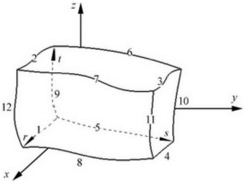
Electromagnetic analysis software usually adopts a hexahedral grid-based processing model, which has high convergence of electromagnetic field radiation, a small amount of calculation, and high efficiency. However, it cannot describe the ejection caused by irregular geometric edge effects in the thermal analysis model, and then Inaccurate thermal radiation calculation

Method used


Image

  • Realization method based on unification of heat-force-electromagnetic field network
  • Realization method based on unification of heat-force-electromagnetic field network
  • Realization method based on unification of heat-force-electromagnetic field network

Examples


Embodiment Construction

[0054] The present invention will be described in detail below in conjunction with specific embodiments. The following examples will help those skilled in the art to further understand the present invention, but do not limit the present invention in any form. It should be noted that those skilled in the art can make several modifications and improvements without departing from the concept of the present invention. These all belong to the protection scope of the present invention.

[0055] The present invention is based on a unified thermal coupling grid and electromagnetic field grid method implemented in the working environment of the chassis thermal effect computing platform, and finally obtains the electromagnetic field data distribution map based on the temperature field distribution and deformation, which helps in multi-physics field conditions Related product design, problem prediction in manufacturing, and accurate simulation analysis, truly realize thermal-electrical-...


PUM


Abstract

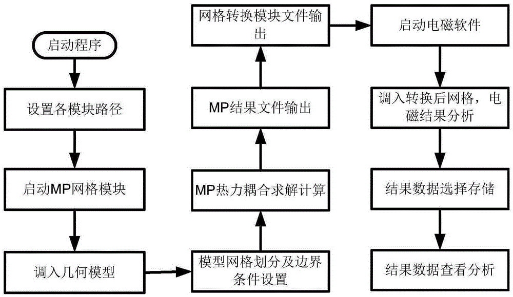
The invention provides a realization method based on unification of a heat-force-electromagnetic field network. The realization method comprises: step 1: performing finite element mesh dividing on a model by using thermal analysis software, so as to obtain a thermal coupling grid of the model; step 2: converting a file format of the thermal coupling grid of the model into a file format which can be identified by electromagnetic software; and step 3: inputting the converted thermal coupling grid file to the electromagnetic software, and performing analysis to obtain thermal field distribution data of the model, so as to obtain an electromagnetic data distribution pattern that is based on temperature field distribution and deformation. According to the realization method provided by the invention, the heat-force-electromagnetic field network is unified; a design scheme can be simulated and verified more accurately and more effectively; system performance is ensured; and a design risk is reduced.

Description

technical field [0001] The invention relates to the field of thermodynamic and electromagnetic analysis, in particular to a realization method based on a unified thermal-mechanical-electromagnetic field network. Background technique [0002] At present, electromagnetic software for solving electromagnetic induced current and voltage, such as ANSOFT; software for calculating fluid and thermal deformation, such as MP; they are all based on different network division processing models, the former adopts mostly hexahedral grid processing models, and the latter Models are processed using mostly triangular meshes. Therefore, the two cannot achieve a unified grid and file format, which means that the one-to-one correspondence between the distribution position of the thermal field and the distribution position of the electromagnetic field cannot be realized. Waiting question. [0003] Since the problem solved and analyzed by the thermal analysis software is based on the tetrahedra...

Claims


Application Information

Patent Timeline
IPC IPC(8): G06F17/50
Inventor 方明龚东磊陈洁段晓峰
Owner NO 32 RES INST OF CHINA ELECTRONICS TECH GRP
Learn More