Plasma water bed cutting platform assembly

A cutting platform and plasma technology, applied in plasma welding equipment, separation methods, filtration and separation, etc., can solve the problems of poor discharge of fine powder on the cutting platform, increase material cost and manufacturing cost, increase labor intensity of workers, etc., and achieve structural Simple, reduces the difficulty of disassembly and assembly, and has the effect of rapid slag discharge

Active Publication Date: 2016-03-16
GUANGZHOU SHIPYARD INTERNATIONAL LTD
View PDF8 Cites 26 Cited by
  • Summary
  • Abstract
  • Description
  • Claims
  • Application Information

AI Technical Summary

Problems solved by technology

[0004] At present, the commonly used plasma water bed cutting platform is a welded structure of the platform plate and the support plate. The platform plate is placed on the pool, and the support plate is welded on the surface of the platform plate to support the steel plate to be cut. There is no water hole on the platform plate. , the water rising and draining in the pool can only be carried out through the gap between the platform plate and the pool. The cutting platform of the above structure has the following disadvantages: (1), the fine powder of the cutting platform is not discharged smoothly, the cutting amount is slightly large, and the cutting slag and The dust is covered with the cutting platform board, and the accumulation is getting higher and higher, which affects the cutting accuracy and the speed of raising water, causing environmental pollution in the workshop, and the dust on the platform must be washed with industrial water every day. During the washing process, the mud flies out of the platform, causing serious damage to Workers bring duplication of labor; (2), when cutting, the top of the support slats will be covered with cutting slag, and iron mud will accumulate on the surface of the platform plate, which cannot be removed by knocking. It increases the labor intensity of the workers. If it is not replaced, it will affect the cutting quality in the later stage. Therefore, most of the time, the cutting platform will be replaced as a whole. According to the calculation of 3m*13m, every time the cutting platform is replaced, it will consume about 8.6 tons of steel, which will increase cost of materials and manufacturing

Method used


Image

  • Plasma water bed cutting platform assembly
  • Plasma water bed cutting platform assembly
  • Plasma water bed cutting platform assembly

Examples


Embodiment Construction

[0033] The technical solutions of the present invention will be further described below in conjunction with the accompanying drawings and through specific implementation methods.

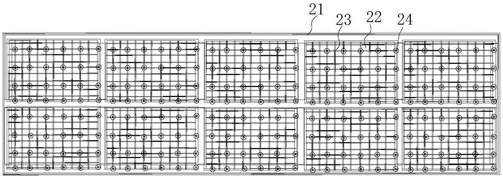
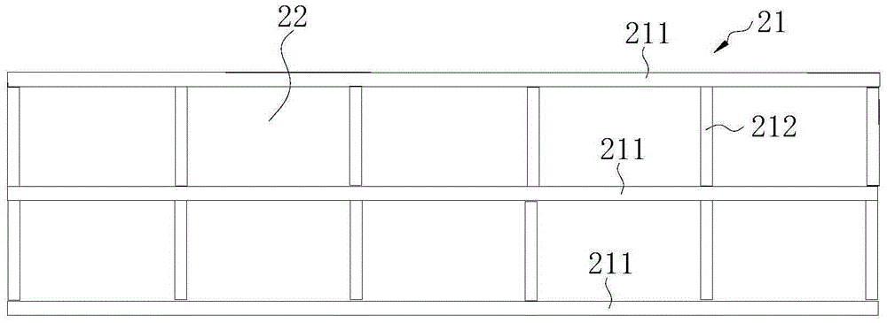
[0034] Such as Figures 1 to 5As shown, in the first embodiment of the present invention, the plasma water bed cutting platform assembly includes a pool 1, a support platform 2, a water baffle 3 and a dust hopper 4, and a double air inlet device and a double exhaust device are arranged in the water pool 1, The support platform 2 is installed obliquely above the pool 1, the water baffle 3 is arranged between the pool 1 and the support platform 2, one end of the water baffle 3 is connected with the dust hopper 4, and the dust hopper 4 is arranged between the support platform 2 and the pool 1 and is located at the inclined lower end of the support platform 2, there is a gap 5 between the dust hopper 4 and the side wall of the pool 1, the support platform 2 includes a frame 21, and a plurality of instal...


PUM


Abstract

The invention discloses a plasma water bed cutting platform assembly. The plasma water bed cutting platform assembly comprises a water tank, a supporting platform, a water-stop sheet and a dust hopper, wherein the supporting platform is slantwise arranged above the water tank along the length direction of the supporting platform; the water-stop sheet is arranged between the water tank and the supporting platform; one end of the water-stop sheet communicates with the dust hopper; a gap exists between the dust hopper and the side wall of the water tank; the dust hopper is arranged between the supporting platform and the water tank and is located at the slantwise low end of the supporting platform; the supporting platform comprises a frame; a plurality of installing locations are uniformly arranged on the frame; a grid plate is detachably arranged at each installing location; a plurality of supporting nails are uniformly distributed on each grid plate along the length direction of the supporting platform; and the lengths of the supporting nails increase sequentially from the high end of the supporting platform to the low end of the supporting platform, so that a horizontal supporting surface is formed at one ends, being far away from the grid plates, of the plurality of supporting nails. The plasma water bed cutting platform assembly has the beneficial effects that the plasma water bed cutting platform assembly is simple in structure, can quickly discharge slag, has low pollution and can be used permanently, the slag is less likely to adhere to the surface of a platform, and cutting platform materials do not need to be changed.

Description

technical field [0001] The invention relates to the technical field of plasma cutting, in particular to a plasma water bed cutting platform assembly. Background technique [0002] Plasma cutting technology refers to the technology that uses highly jetted ionized gas to jet out from the compressed gas port to achieve the cutting effect. The parts are cut and then the metal is melted, and the molten metal is mechanically blown away by the high-speed and high-pressure ion gas flow, and a kerf is formed as the torch moves. [0003] Compared with traditional stamping, cutting and even laser cutting processes, plasma cutting machine has the characteristics of strong flexibility, small processing traces, high precision, small incision, reduced facet angle, bevel cutting, high-quality trimming, etc., so plasma Cutting machines are used more and more widely in various industries. [0004] At present, the commonly used plasma water bed cutting platform is a welded structure of the p...

Claims


Application Information

Patent Timeline
IPC IPC(8): B23K10/00B01D29/03B01D47/02
CPCB01D29/03B01D47/02B01D2029/033B23K10/00
Inventor 唐合成张兴国杨茨祥舒海威何志敏薛焯名张沪生
Owner GUANGZHOU SHIPYARD INTERNATIONAL LTD
Why Eureka
Try Eureka