
Semi-open type full circumferential coronagraph apparatus with large field of view

A semi-open, large field of view technology, applied in the direction of instruments, optical components, optics, etc., to reduce weight, reduce scattered stray light, and reduce the effect of scattered stray light

Inactive Publication Date: 2016-03-09
SHANDONG UNIV +1
View PDF4 Cites 10 Cited by
  • Summary
  • Abstract
  • Description
  • Claims
  • Application Information

AI Technical Summary

Problems solved by technology

The above-mentioned coronagraph designs the heat-rejecting mirror as a concave mirror structure, which reflects the stray light out of the optical system and eliminates the influence of the stray light on the wall of the lens barrel on the infrared band. , but the reflection focus of the heat-rejecting mirror is actually the position between the outer diaphragm and the outer shielding body, and the stray light is not reflected out of the lens barrel, so the light reflected by the heat-rejecting mirror cannot avoid reflection in the lens barrel And enter the objective lens to generate stray light, which affects the accuracy of coronal observation
[0005] Moreover, in the traditional coronagraph and the above-mentioned prior art coronagraph structures, the coronagraph structure is usually designed as a cylinder, mainly because the lenses of the coronagraph are usually circular, so when designing the field of view, the apertures are all circular, that is, the current Technical bias of cylindrical coronagraphs in existing technologies

Method used


Image

  • Semi-open type full circumferential coronagraph apparatus with large field of view
  • Semi-open type full circumferential coronagraph apparatus with large field of view
  • Semi-open type full circumferential coronagraph apparatus with large field of view

Examples


Embodiment 1

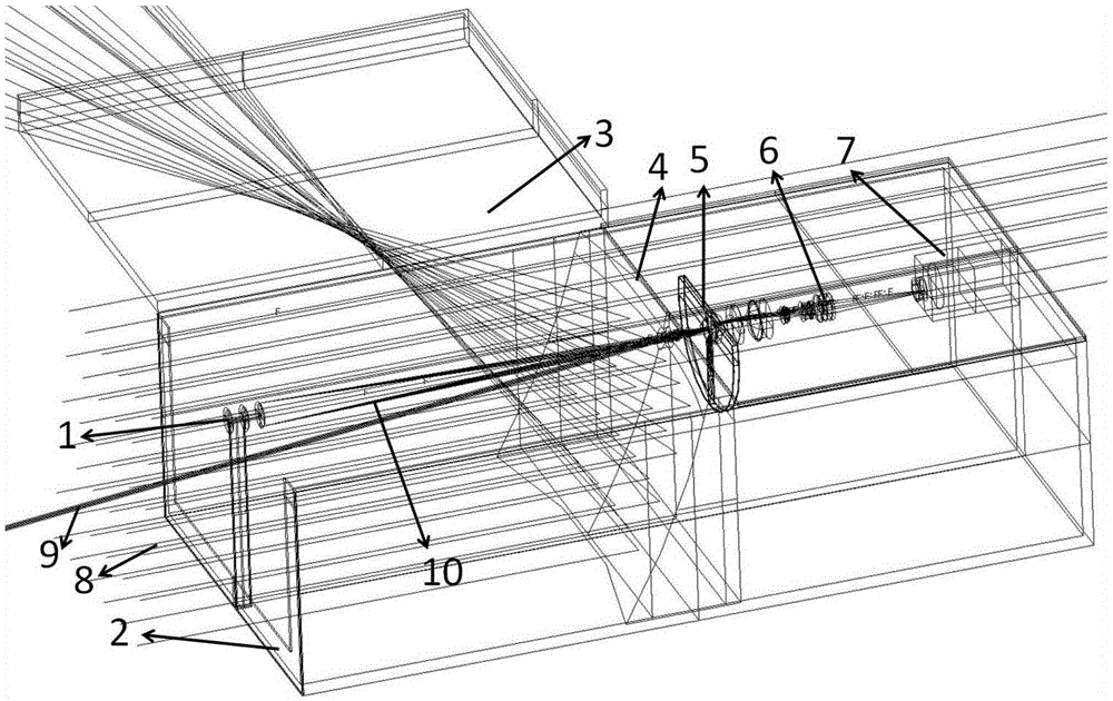
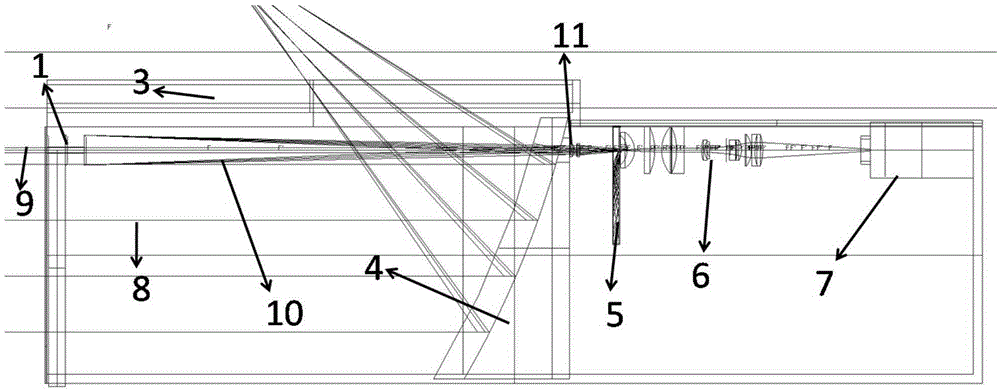
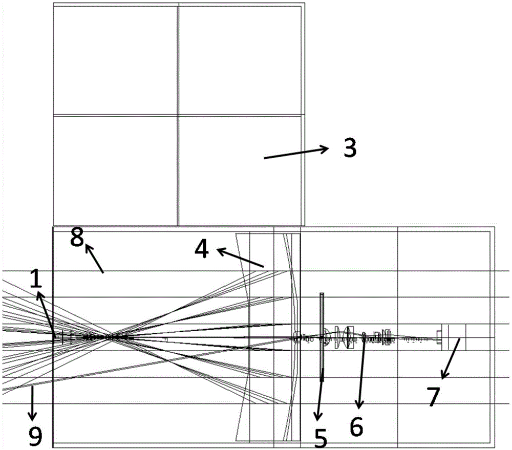
[0028] see Figure 1-Figure 3 , the present invention discloses a semi-open full-circumferential large field of view coronagraph device. The coronagraph device includes an outer shelter 1, an outer window 2, a heat-repelling mirror 4, an inner shelter 12, and an inner shelter light absorption groove from left to right. 5. Imaging system 6 and CCD camera 7.

[0029] The coronagraph device has a semi-open square structure as a whole, and the outer window 2 is arranged on the left side of the square structure. The outer window 2 has a U-shaped aperture with an upper end opening, and direct sunlight enters the optical system from the left side of the outer window 2 . The diffraction light intensity of the U-shaped aperture of the square structure at the center of the back field is smaller than that of the circular aperture of the cylindrical structure, which can be calculated according to the Fresnel Kirchhoff diffraction integral formula 1.1, and the Fresnel Kirchhoff diffraction...


PUM


Abstract

The invention relates to a semi-open type full circumferential coronagraph apparatus with a large field of view. The coronagraph apparatus comprises in sequence from left to right: an outer shielding body, an outer window, a heat collecting lens, an inner shielding body, an inner shielding body light-absorbing groove, an imaging system and a CCD camera. The outer shielding body and the inner shielding body are disposed on the optical axis of an optical path. The inner shielding body is positioned in an imaging position where the outer shielding body passes through an object lens unit. The coronagraph apparatus, as a whole, is of a semi-open square structure, and is reduced in size and weight. The heat collecting lens is a reflector with a square centrally-recessed structure, and the recessed surface of the centrally-recessed structure faces one side of the outer window. The heat collecting lens is arranged in an inclined manner. The lower end of the heat collecting lens goes toward one side of the outer window relative to the upper end of the heat collecting lens. Incident sun direct light is focused by the heat collecting lens outside the semi-open square structure, so the influence of scattered stray light on the surface of the heat collecting lens is reduced.

Description

technical field [0001] The invention relates to a corona observation device, in particular to a semi-open full-circumferential large-field coronagraph device. Background technique [0002] At present, the maximum field of view of coronagraphs for full-circumferential observation in the world is 30R⊙, where R⊙ represents the radius of the sun. The distance between the sun and the earth is 215R⊙, and the full-circumference observation of the corona and coronal mass ejection events in this space can be used to study the influence of the sun's magnetic field on the earth. At present, there is no coronagraph for full-circumferential observation of the corona and coronal mass ejection phenomena in this space. There are two main factors restricting the observation of the entire circumference of the corona: 1. The large field of view will lead to a large volume of the coronagraph, and at the same time lead to excessive weight, both of which will increase the carrying burden of the ...

Claims


Application Information

Patent Timeline
Patent Type & Authority Applications(China)
IPC IPC(8): G02B27/02
CPCG02B27/022
Inventor 孙明哲张红鑫夏利东刘维新卜和阳
Owner SHANDONG UNIV
Learn More