
Air-tight fiber wall-penetrating socket

An air-tight, optical fiber technology, applied in optics, light guides, optical components, etc., can solve the problems of inability to process, easily damaged optical fibers, low qualification rate, etc., and achieves easy processing and assembly, large number of channels, and good air tightness. Effect

Inactive Publication Date: 2016-03-09
SHANGHAI AEROSPACE SCI & IND ELECTRIC APPLIANCE RES INST
View PDF5 Cites 4 Cited by
  • Summary
  • Abstract
  • Description
  • Claims
  • Application Information

AI Technical Summary

Problems solved by technology

The existing problems are, firstly, because the epoxy glue bonded to the optical fiber and the ceramic ferrule and the optical fiber itself are not resistant to high temperature, when the number of cores of the optical fiber wall socket is large, the glass sintering process is easy to damage the optical fiber. In addition, the ferrule The grinding and assembly process is extremely complicated, which cannot meet the needs of mass production. Second, the existing optical fiber air-tight wall sockets mostly use slender and whole ceramic pins, which makes the processing of the slender pins difficult and the pass rate is high. Low, when the length and diameter reach a certain ratio, it cannot be processed at all, which restricts the miniaturization and integrated development of optical fiber hermetic through-wall sockets.

Method used


Image

  • Air-tight fiber wall-penetrating socket
  • Air-tight fiber wall-penetrating socket
  • Air-tight fiber wall-penetrating socket

Examples


Embodiment Construction

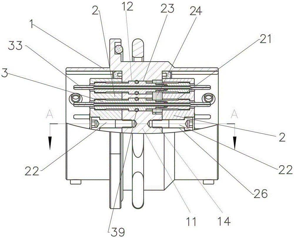
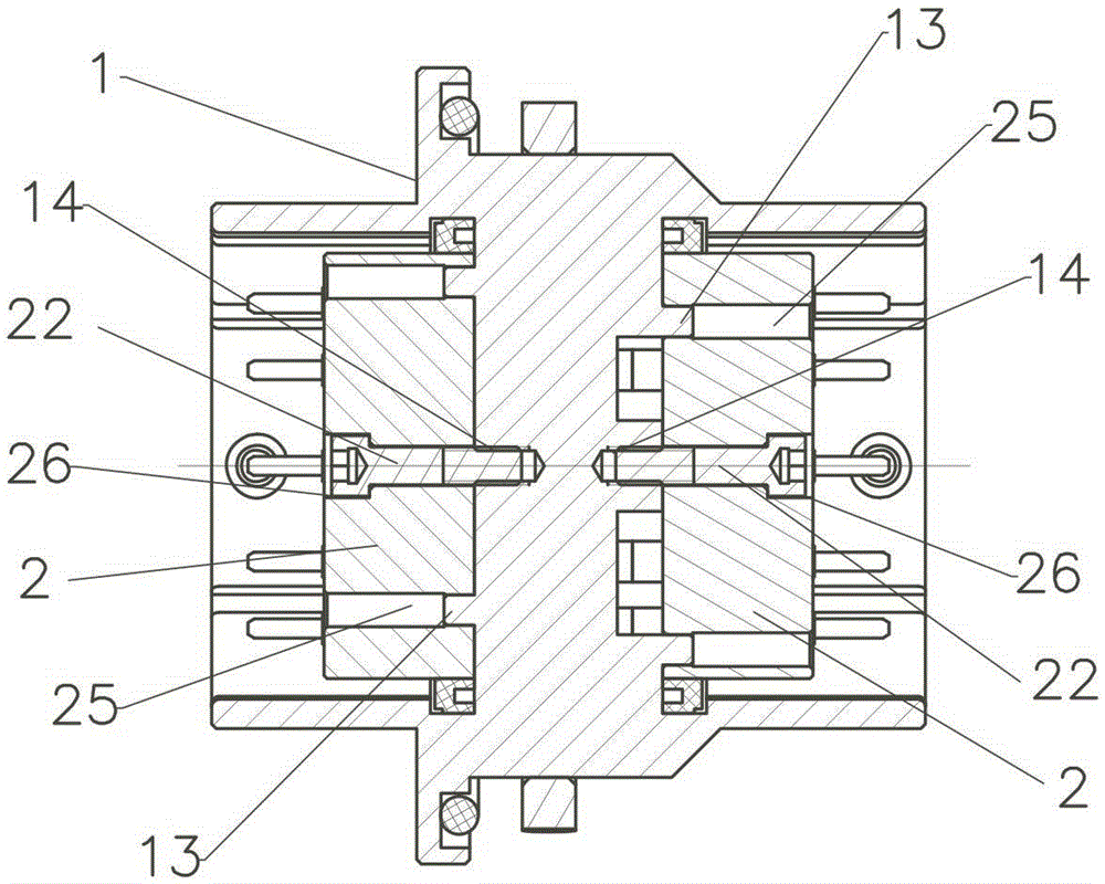
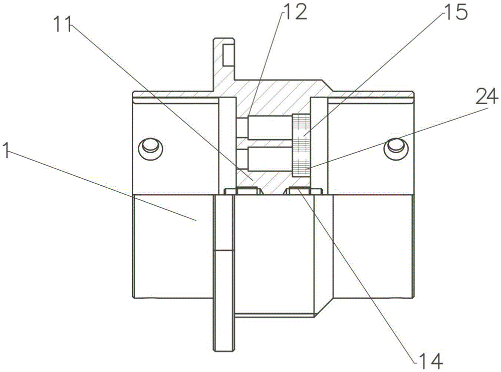
[0015] refer to figure 1 , figure 2 , image 3 , Figure 4 , Figure 5 , the present invention includes:

[0016] A cylindrical housing 1 with a partition wall 11 in the middle, several pin limit holes 12 are provided on the partition wall 11, a silicone groove 15 is provided on one end of the partition wall 11, and positioning bosses 13 and screw threads are provided on both ends of the partition wall 11. Blind hole 14; a pressure plate 2 provided with a pin step hole 21, a positioning hole 25 and a screw counterbore 26 respectively corresponding to the pin limit hole 12 of the housing 1, the positioning boss 13 and the threaded blind hole 14; There is a ferrule assembly 3 with a front sleeve 31, a rear sleeve 32, a ceramic ferrule 33 and a tightly wrapped optical fiber 36; The hole 35 and the boss 37, the tight-packed optical fiber 36 are located in the tube holes of the front sleeve 31 and the rear sleeve 32, and the ceramic insert pins 33 are two pieces, and are resp...


PUM


Abstract

The invention discloses an air-tight fiber wall-penetrating socket. The air-tight fiber wall-penetrating socket is characterized by comprising: a housing having a separation wall provided with multiple pin limit holes; press plates with pin stepped holes, positioning holes and screw counterbores; and pin assemblies provided with front sleeve pipes, rear sleeve pipes, ceramic pins and tight coated fibers. The pin assemblies are disposed in the pin limit holes of the housing. The two press plates are disposed on the two sides of the separation wall of the housing respectively. The pin assemblies are inserted in the pin stepped holes. The positioning holes of the press plates fit positioning bosses of the housing. The screw counterbores are connected to threaded blind holes by means of screws. Through adoption of the housing, the press plates and the pin assemblies and also through the assembly process using an epoxy sealant and silica gel, a present situation that long and thin pins are difficult to process is avoided. The advantages are that the air-tight fiber wall-penetrating socket has many channels, exhibits good air-tightness, and is convenient to process and assemble.

Description

technical field [0001] The invention relates to the technical field of optical fiber connectors, in particular to an airtight optical fiber wall socket. Background technique [0002] The purpose of using optical fiber connectors to connect with equipment is to make the optical fibers passing through the equipment panel not only withstand the pressure difference inside and outside the panel, but also prevent the interpenetration of the media inside and outside the panel, that is, there is a requirement for airtightness of the optical fiber connector. With the increasing application of optical fiber communication technology in aerospace and harsh environments, the technical requirements for the airtightness of optical fiber connectors are also gradually increasing. In the prior art, the optical fiber hermetic wall socket is generally sealed with glue or an "O" ring, and its sealing level is low; there are also optical fiber airtight wall sockets that are sealed with glass sint...

Claims


Application Information

Patent Timeline
Patent Type & Authority Applications(China)
IPC IPC(8): G02B6/38
CPCG02B6/3825G02B6/3849
Inventor 赵苏琨张光陈惠钦
Owner SHANGHAI AEROSPACE SCI & IND ELECTRIC APPLIANCE RES INST
Learn More