
Condenser safety diaphragm plate for detecting trace leakage

A condenser and micro-quantity technology, applied in the direction of measuring the increase and decrease rate of fluid, steam/steam condenser, liquid tightness measurement using liquid/vacuum degree, etc., can solve the problem of steam turbine device efficiency, power influence, safety film Problems such as bulging, puncture or puncture not touching, etc., to achieve the effect of efficient and safe equipment work, prevention of sharp instrument stabbing, and more efficient equipment work

Active Publication Date: 2016-03-09
HANGZHOU GUONENG STEAM TURBINE ENGINEER
View PDF8 Cites 4 Cited by
  • Summary
  • Abstract
  • Description
  • Claims
  • Application Information

AI Technical Summary

Problems solved by technology

[0004] After the existing steam turbine condenser is installed, the shell side needs to be filled with water to detect leaks or when abnormal positive pressure occurs during operation, the safety template of the condenser for detecting trace leaks may be damaged due to the effect of water pressure or steam pressure Diaphragm bulges, or even ruptures, making it difficult to establish vacuum pressure at the exhaust part, affecting the normal operation of the steam turbine unit
[0005] Because the safety diaphragm is installed in a confined space, it is inconvenient for the outside to observe and check whether it is broken
When the rupture of the safety diaphragm is large, it is easy to judge due to the difficulty in establishing the internal vacuum, but when the rupture of the safety diaphragm is small and the air leakage is not large, it is very difficult to judge due to the large size of the entire system, which affects the efficiency of the steam turbine. There are security risks
[0006] Chinese patent literature discloses a safety diaphragm that can monitor the deformation of the diaphragm [patent number: ZL201220404766.2; authorization announcement number: CN202734595U]; When the pressure is positive, the detection of the deformation of the diaphragm touches the travel switch to give an alarm. This solution can meet the general application requirements, but the reliability needs to be further improved when the diaphragm deformation is stabbed by a sharp object in the structure or does not touch the travel switch. coefficient and a more timely and detailed understanding of the state of the diaphragm; for example, it is necessary to judge the state and causes of the diaphragm more clearly to prevent misjudgment, especially to detect the small rupture of the diaphragm caused by various reasons. Leakage should not be detected, but it has a great impact on the efficiency and power of the steam turbine device

Method used


Image

  • Condenser safety diaphragm plate for detecting trace leakage
  • Condenser safety diaphragm plate for detecting trace leakage
  • Condenser safety diaphragm plate for detecting trace leakage

Examples


Embodiment 1

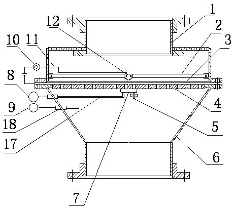
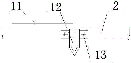
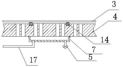
[0033] Such as figure 1 As shown, a condenser safety template for detecting trace leaks includes an upper shell 1 communicating with the atmosphere, a lower shell 6 for communicating with the inner cavity of the condenser, and the lower shell 6 and the end surface of the upper shell 1 For docking, a safety diaphragm 3 is provided between the lower housing 6 and the upper housing 1 to isolate the chambers of the upper and lower housings. Such as figure 2 As shown, a sharp 12 is fixed above the safety diaphragm 3 , a beam 2 is fixed on the upper housing 1 , the sharp 12 is fixed in the center of the beam, and an insulating layer 13 is arranged between the beam 2 and the sharp 12 . Both the safety diaphragm 3 and the sharps 12 are made of metal, and the tip of the sharps 12 points to the safety diaphragm 3 and keeps a certain distance from the safety diaphragm 3; A through hole for connecting the upper and lower spaces is arranged on the top, and the edge of the supporting ori...

Embodiment 2

[0038] The difference from Example 1 is:

[0039] like Figure 4 As shown, the supporting orifice plate is composed of a flange 19 provided with a grid 16 and a punching plate 15 arranged on the flange. like Figure 5 As shown, the sampling chamber is set in the middle of the flange, several grilles are connected between the sampling chamber and the flange, and a sealing ring is set between the port of the sampling chamber and the punching plate. It plays a certain supporting role for the safety template, and the gas cannot enter the sampling chamber through the gap between the two. Unless the template bulges and there is a gap between the two, the gas in the lower shell will enter the sampling chamber. The perforated plate is made of stainless steel.

[0040] In addition, if it is inconvenient to use pipelines to communicate with the sampling chamber and the lower casing, it is also possible to arrange sensitive pressure sensors in the sampling chamber 7 and the lower casi...


PUM


Abstract

The invention provides a condenser safety diaphragm plate for detecting trace leakage. The condenser safety diaphragm plate can monitor deformation and tiny cracks of a safety diaphragm. The condenser safety diaphragm plate for detecting trace leakage comprises an upper shell communicated with air and a lower shell communicated with a condenser inner cavity. The end face of the lower shell is in butt joint with the end face of the upper shell, and the safety diaphragm is arranged between the lower shell and the upper shell. A sharp instrument is fixedly arranged above the safety diaphragm, and the sharp end of the sharp instrument points to the safety diaphragm and spaced with the safety diaphragm by a certain distance. A supporting pore plate is arranged below the safety diaphragm. A sampling chamber corresponding to the sharp instrument is arranged on the supporting pore plate. Sealing rings are arranged between the sampling chamber and the safety diaphragm. Pressure measurement devices are arranged on the sampling chamber and the lower shell. A capacitance measurement device is connected between the sharp instrument and the safety diaphragm. The condenser safety diaphragm plate is simple in structure and low in cost, the deformation degree of the safety diaphragm can be detected, and the situation that the safety diaphragm excessively deforms and is punctured by the sharp instrument is avoided. In the work process of a condenser, the tiny cracks of the safety diaphragm can be detected.

Description

technical field [0001] The invention relates to a safety protection device for a negative pressure container, in particular to a condenser safety template capable of monitoring the deformation and micro-rupture of a safety diaphragm of a steam turbine condenser and detecting micro-leakage. Background technique [0002] When the condensing steam turbine works, the shell side of the condenser is required to be in a vacuum state, and its vacuum degree has a great influence on the efficiency and power of the steam turbine device. [0003] When the condensing steam turbine is in an abnormal working state, positive pressure may appear in the shell side of the condenser, which will have an adverse effect on the equipment and even endanger the safety of the equipment. Therefore, a condenser safety template is installed on the condenser shell side to detect small leaks; the safety diaphragm in the device can burst when the internal pressure is 0.01 to 0.02MPa to release the positive ...

Claims


Application Information

Patent Timeline
IPC IPC(8): F28B9/00G01M3/32
Inventor 张立明钱敏强黄建平
Owner HANGZHOU GUONENG STEAM TURBINE ENGINEER
Learn More