A kind of manufacturing method of permanent magnet ferrite

A technology of permanent magnet ferrite and manufacturing method, applied in the direction of magnetism of inorganic materials, etc., can solve the problems of easy cracking, poor product performance, etc., and achieve the effects of not easy to agglomerate, improve magnetic field orientation, and narrow particle size distribution range.

Active Publication Date: 2017-08-01
霍山东磁电子科技有限公司
View PDF5 Cites 2 Cited by
  • Summary
  • Abstract
  • Description
  • Claims
  • Application Information

AI Technical Summary

Problems solved by technology

[0005] In order to solve the problem of easy cracking of permanent magnet ferrite during sintering and poor product performance after sintering in the prior art, the present invention provides a method that can effectively prevent cracking of permanent magnet ferrite during sintering, improve product quality, and improve the overall performance of the product. Manufacturing method of permanent magnet ferrite

Method used


Image

  • A kind of manufacturing method of permanent magnet ferrite
  • A kind of manufacturing method of permanent magnet ferrite

Examples


Embodiment 1

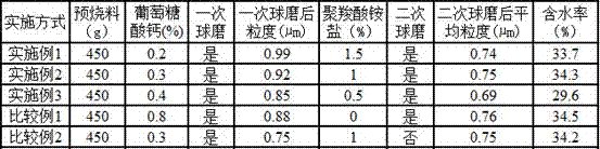
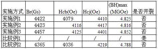
[0020] Embodiment 1: the permanent magnet ferrite pre-fired material is passed through 300 mesh sieve screening processes, get the permanent magnet ferrite pre-fired material 450g that cannot pass through the hole purpose, and the following mass percentages are all based on the quality of the 450g permanent magnet pre-fired material, Add 0.4% SiO2 and 0.6% CaCO3 in the form of mass percentage to obtain a mixture; add 0.2% calcium gluconate in the mixture to carry out wet ball milling, and the diameter of steel balls in wet ball milling D1=6.6 µm, grind for 12 hours to obtain a primary grinding slurry with an average particle size of 0.85-1.0 μm. After taking out the primary grinding slurry, add 1.5% polycarboxylate ammonium salt and carry out wet ball milling. The polycarboxylate ammonium salt The carbon chain length is 5-10 C, the diameter of the steel ball in wet ball milling is D2=3µm, and the grinding time is 8 hours to obtain a secondary abrasive with an average particle s...

Embodiment 2

[0021] Embodiment 2: the mass percent of calcium gluconate is 0.3%, the mass percent of polycarboxylate ammonium salt is 1%, the magnetic field size of orientation setting is 12000GS, and the shaped body after setting is incubated at 115 ℃ for 1.25h, then heats up to Insulate at 450°C for 2.25h, then raise the temperature to 1223°C for 1.5h, and the rest of the steps are the same as in Example 1.

Embodiment 3

[0022] Embodiment 3: the mass percentage of calcium gluconate is 0.4%, the mass percentage of polycarboxylate ammonium salt is 0.5%, the magnetic field size of orientation setting is 14000GS, and the shaped body after setting is incubated at 130 ℃ for 1h, and then heated up to 500 ℃ for 2 hours, and then heated up to 1220 ℃ for 1 hour, and the rest of the steps are the same as in Example 1.


PUM

PropertyMeasurementUnit
particle sizeaaaaaaaaaa

Abstract

The invention relates to the technical field of permanent magnetic ferrites, in particular to a manufacturing method of a permanent magnetic ferrite. The manufacturing method comprises the following steps of taking a certain mass of permanent magnetic ferrite preburning materials, and adding 0.3-0.5% of SiO2 and 0.5-0.7% of CaCO3 in percentage by mass; adding 0.2-0.4% of calcium gluconate to a mixed material, and using a steel ball of which the diameter is D1 for performing wet-method ball milling so as to obtain a primary grinding sizing material; taking out the primary grinding sizing material, adding 0.5-1.5% of polyocarboxy acid ammonium salt in percentage by weight, and using a steel ball of which the diameter is D2 for performing wet-method ball milling so as to obtain a secondary grinding sizing material, wherein D1 is greater than D2; performing dehydration treatment on the secondary grinding sizing material, loading the dehydrated sizing material into a mold, performing orientation shaping under a magnetic field of 10000-14000GS, and then performing sinter molding. The manufacturing method disclosed by the invention has the beneficial effects that the permanent magnetic ferrite is prevented from being cracked when being sintered, the product quality is improved, and the overall performance is improved.

Description

technical field [0001] The invention relates to the technical field of permanent magnet ferrite, in particular to a method for manufacturing permanent magnet ferrite. Background technique [0002] In the past two decades, ferrite materials, as one of the electronic functional materials, have played an important role in various industries such as information storage, automatic control, electromechanical, communication, and military industry, and their development is also very rapid. At present, the ceramic method is more common in the production of permanent magnet ferrite materials, and its main technical characteristics are based on Sr ferrite, and the performance is improved through La-Co combined ion substitution. The magnetic properties of permanent magnet materials mainly include three parameters: residual magnetic flux density (Br), intrinsic coercive force (Hcj) and maximum energy product (BH)max. In order to obtain high-performance products, it is very important to ...

Claims


Application Information

Patent Timeline
Patent Type & Authority Patents(China)
IPC IPC(8): H01F1/10C04B35/26C04B35/634
Inventor 郭超阳杨武国胡江平金志洪徐君
Owner 霍山东磁电子科技有限公司
Why Eureka
Try Eureka