
Manufacturing method of glass particle stack

A glass particle and manufacturing method technology, applied in glass manufacturing equipment, glass molding, manufacturing tools, etc., can solve the problem of glass particle stack outer diameter change, etc., and achieve the effect of preventing interface irregularities

Active Publication Date: 2018-12-04
SUMITOMO ELECTRIC IND LTD
View PDF7 Cites 0 Cited by
  • Summary
  • Abstract
  • Description
  • Claims
  • Application Information

AI Technical Summary

Problems solved by technology

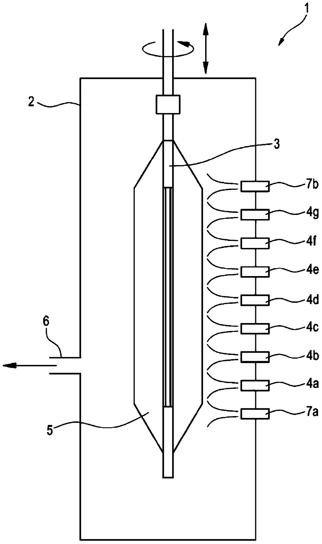
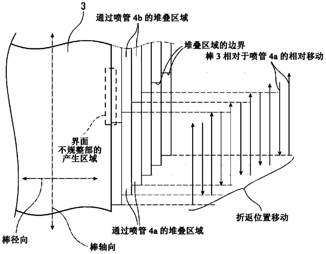
In the MMD method, the outer diameter of the glass particle stack may vary due to overlapping stacking positions or an increase in the stacked amount of glass particles at the return position of the reciprocating movement.

Method used


Image

  • Manufacturing method of glass particle stack
  • Manufacturing method of glass particle stack
  • Manufacturing method of glass particle stack

Examples


Embodiment 1

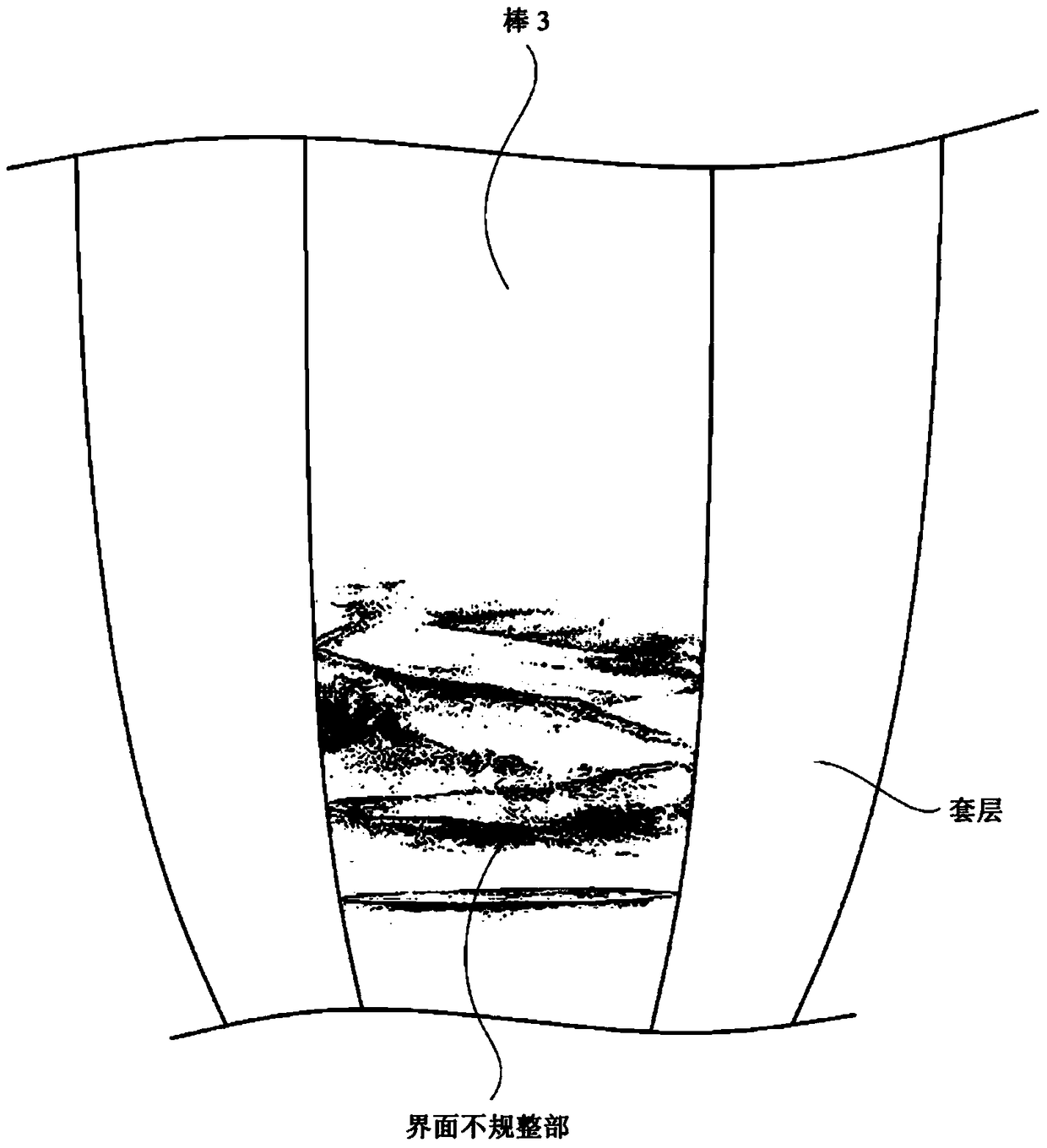
[0028] The number of interference layers from the rod interface (one layer is stacked in one reciprocation movement) was changed, and the glass fine particle stacks 5 were each produced by the production method according to the embodiment of the present invention. Then, the presence or absence of interface irregularities and the presence or absence of unsintered portions were investigated for each of the manufactured glass fine particle stacks 5 . express the result in Image 6 , Figure 7 middle. In addition, in Example 1, the ratio of the flow rate of hydrogen gas which will be described later was set to 1.17.

[0029] Image 6 It is a graph showing the relationship between the ratio of the interference layer to the total number of laminations per glass particle stack and the incidence of interface irregularities. according to Image 6It can be seen that when the ratio of the interference layer to the total number of laminations is about 0.2% or more, there is an effect...

Embodiment 2

[0032] The bulk density of the glass particle stack is proportional to the flow rate of the combustible gas in the nozzle, so the flow rate of the combustible gas, that is, hydrogen gas (hydrogen and oxygen gas is used in the flame formation of the nozzle in this embodiment) was changed, and the investigation The occurrence rate of interface irregularities due to the difference in packing density of the interference layer. When the number of layers of the interference layer from the rod interface is set constant (3 layers), and the flow rate of the hydrogen gas in the nozzles 4a to 4g is changed when forming the interference layer, and using the production method according to the embodiment of the present invention, respectively Production of the glass fine particle stacked body 5 is performed. Then, the presence or absence of interface irregularities was investigated for each of the produced glass fine particle stacks 5 . Figure 8 is the ratio of the flow rate of hydrogen g...


PUM


Abstract

The invention provides a manufacturing method for a glass particle stack which will not have external diameter changes at a fold-back position of reciprocating movements of a rod and prevent occurrence of an interface irregular portion. When stacking of glass particles begins, the fold-back position of the reciprocating movements is fixed, and on the position a plurality of interference layers is stacked. After the plurality of interference layers is stacked, in each reciprocating movement, the fold-back position is made to move and glass particle stacking is carried out.

Description

technical field [0001] The present invention relates to a method for manufacturing a glass particle stack. Background technique [0002] There is known a method of manufacturing a glass particle stack by using a multi-nozzle multilayer spray deposition method (MMD method) in which a rotating rod and a row of a plurality of nozzles arranged opposite to the rod are relatively reciprocated, Glass particles generated by a nozzle are blown onto the surface of the rod to be stacked in layers. In the MMD method, there is a possibility that the outer diameter of the stacked body of glass particles may fluctuate due to overlapping stacking positions or an increase in the stacking amount of glass fine particles at the return position of the reciprocating movement. Therefore, a method of adjusting the rotation speed of the rod has been proposed (for example, refer to Japanese Patent Application Laid-Open No. 2013-43810), a method of moving the reciprocating turning position (for examp...

Claims


Application Information

Patent Timeline
Patent Type & Authority Patents(China)
IPC IPC(8): C03B19/14
CPCC03B37/0142C03B2207/52C03B2207/66C03B2207/70
Inventor 楠浩二
Owner SUMITOMO ELECTRIC IND LTD
Learn More