Wet high-speed rotating motor with double-toothed stator and rotor

A high-speed rotation, stator-rotor technology, applied in the direction of electromechanical devices, electrical components, electric components, etc., can solve the problems of short bearing life, high heat generation, dynamic sealing of motors, etc., achieve low cost, increase service life, and reduce friction The effect of resistance

Inactive Publication Date: 2016-03-02
ZHEJIANG UNIV OF TECH
View PDF6 Cites 3 Cited by
  • Summary
  • Abstract
  • Description
  • Claims
  • Application Information

AI Technical Summary

Problems solved by technology

[0004] In order to overcome the shortcomings of existing high-speed motors such as high heat generation, short bearing life, and dynamic sealing required for the motor, the present invention provides a stator-rotor double-geared wet high-speed rotating motor that can circulate cooling rotors, have long bearing life, and do not require dynamic sealing for the motor.

Method used


Image

  • Wet high-speed rotating motor with double-toothed stator and rotor
  • Wet high-speed rotating motor with double-toothed stator and rotor
  • Wet high-speed rotating motor with double-toothed stator and rotor

Examples


Embodiment 1

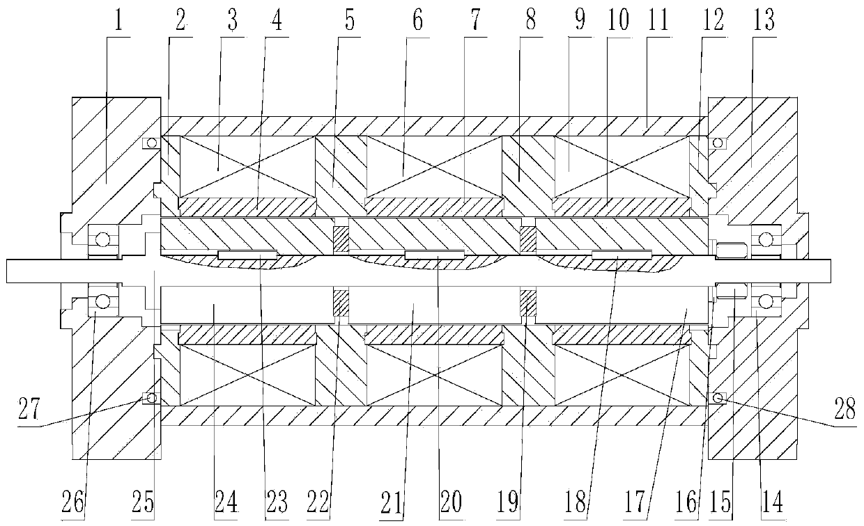
[0033] Embodiment 1 The stator and rotor double-tooth wet high-speed rotating electric machine of the present invention includes a stator part, a rotor part, a front end cover 1 with an oil inlet and a rear end cover 13 with an oil outlet. The front , The back end cover is respectively sealed and installed at the two ends of the stator part, the two ends of the rotor part are respectively axially connected with the corresponding front and back end covers, and the stator part includes a magnetic sleeve 11, a stator Components, the two ends of the stator component are respectively fixedly connected to the corresponding front and rear end covers; the magnetic sleeve is located on the outer ring of the stator component;

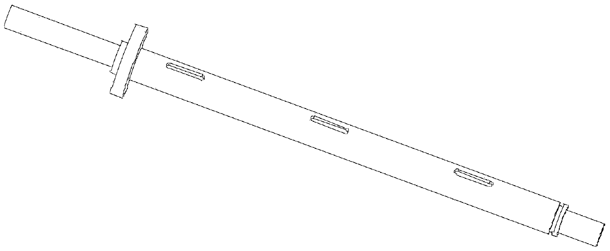
[0034] The rotor part includes a rotor shaft 25, a rotor first section 24 sleeved outside the rotor shaft, a second rotor section 21, a third rotor section 17 and a magnetic isolation ring (22, 19). Three rotors (24, 21, 17) arranged along the axis of the rotor are ...

Embodiment 2

[0044] Example 2 Refer to Figure 1~ Figure 12b , A wet high-speed rotating electric machine for a variable-speed hydraulic pump, comprising a stator part, a rotor part, a front end cover 1 and a rear end cover 13. The stator part is located outside the rotor part, and the rotor part includes a flat key, a nut, and a gasket. The sheet, the magnetic isolation ring, the first rotor section 24, the second rotor section 21, the third rotor section 17 and the rotor shaft. The first rotor section 24, the second rotor section 21 and the third rotor section 17 are mounted on the rotor shaft 25 , The two ends of the rotor shaft 25 are respectively mounted on the front end cover 1 and the rear end cover 13; the first stator core 2, the second stator core 5, the third stator core 8, the fourth stator core The cores 12 are in an annular shape. The first stator core 2, the second stator core 5, the third stator core 8, and the fourth stator core 12 are all arranged on the outer ring of the r...


PUM


Abstract

The invention provides a wet high-speed rotating motor with a double-toothed stator and rotor. The wet high-speed rotating motor comprises a stator part, a rotor part, a front end cover with an oil inlet, and a rear end cover with an oil outlet, wherein the front end cover and the rear end cover are respectively mounted at the two ends of the stator part in a sealed way, the stator part is arranged at the outer ring of the rotor part, the two ends of the rotor part are respectively connected to the corresponding front and rear end covers in a coupling way, the stator part comprises a flux sleeve and a stator component, the two ends of the stator part are respectively connected with the corresponding front and rear end covers fixedly, and the flux sleeve is arranged at the outer ring of the stator part. The wet high-speed rotating motor has the main beneficial effects that an axial phase split is adopted to ensure simple structure and low cost; the lubricating manner is simple and reliable and is low in cost; the problem that the motor generates a large quantity of heat when the motor rotates at a high speed can be solved and therefore the continuous working time of the motor is prolonged.

Description

Technical field [0001] The invention belongs to an electric-mechanical energy conversion device for variable-speed hydraulic pumps in the field of fluid transmission and control, and in particular relates to a stator-rotor double-open tooth wet-type high-speed rotating electric machine. Background technique [0002] There are two ways to change the flow of a hydraulic pump. One is to change the flow of the pump by changing the displacement of the pump, which is a variable pump in the ordinary sense; the other is to adjust the flow of the pump by directly changing the speed of the pump through a variable frequency motor. , Which is the so-called variable speed pump. Because variable mechanisms are generally more complex and costly, with the development of power electronics technology, variable speed pumps have very bright application prospects in hydraulic engineering. [0003] To achieve large flow for variable speed pumps, high-speed variable frequency motors are the key. Only w...

Claims


Application Information

Patent Timeline
Patent Type & Authority Applications(China)
IPC IPC(8): H02K1/16H02K1/22H02K5/16H02K9/19H02K5/20
Inventor 阮健申屠胜男金丁灿陈烜孟彬
Owner ZHEJIANG UNIV OF TECH
Why Eureka
Try Eureka